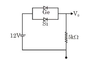
Calculate the value of output voltage `V_(0)` (in V) if the Si diode and Ge diode conduct at `0.7V` and `0.3 V` respectively. Fig.
Text Solution
Verified by Experts
The correct Answer is:
11.7
(i) As germanium diode conducts at lower voltage (0.3V) than silicon diode which conduct at 0.7 V, so the current will prefer to pass through germanium diode. Then output voltage, `V_(0)=12-0.3=11.7V` and current, `I=V_(0)/R=11.7/(5xx10^(3))=2.34xx10^(-3)A=2.34mA` (ii) When germanium diode is reverse biased, it will offer very large resistance to the current flowing through it. Now the current will flow through the silicon diode. Then output voltage, `V_(0)=12-0.7=11.3V` and current, `I=V_(0)/R=11.3/(5xx10^(3))=2.26xx10^(-3)A` `=2.26mA`
Topper's Solved these Questions
ELECTRONIC DEVICES
PRADEEP|Exercise SAMPLE PROBLEM|2 Videos
ELECTRONIC DEVICES
PRADEEP|Exercise CONCEPTUAL PROBLEMS|1 Videos
ELECTROMAGNETIC WAVES
PRADEEP|Exercise II Focus multiple choice question|5 Videos
ELECTROSTATICS
PRADEEP|Exercise ASSERTION-REASON TYPE QUESTIONS|2 Videos
Similar Questions
Explore conceptually related problems
Calculate the value of output voltage V_(0) and I if the Si diode and the Ge diode conduct at 0.7 V and 0.3V respectively, in the circuit given in Fig. If now Ge diode connections are reversed, what will be the new values of V_(0) and I.
Calculate the value of V_(0) and I If the Si diode and the Ge diode start conducting ar 0.7 V and 0.3 volt respectively. In the given circuit. If the Ge diode connection be reversed. What will the new value of V_(0) and I ? .
What is the value of output voltage V_(0) in the circuit shown in the figure ?
What is the value of output voltage V_0 in the circuit shown in the figure ?
In the circuit shown in figure, the silicon and germanium diodes start conducting at 0.7 V and 0.3 V respectively. What are the values of V_0 and I?
A silicon diode is connected to a load resistance R_(L) as shown in the figure. If V_(in)=15V and R_(L)=10kOmega (a) If barrier voltage, V_(B)=0.7V then calculate (i) output voltage across R_(L) (ii) current in diode and ltbRgt (iii) forward resistance. (b) If diode is assumed ideal, then what will be (i) output voltage and (ii) output current in diode?
Find the voltage V_(A) in the curcuit shown in figure. The potential barrier for Ge is 0.3 V and for Si is 0.7 V .
In the circuit shown in figure the maximum output voltage V_(0) is
Two Zener diodes (A and B ) having breakdown voltage of 6 V and 4 V respecitvely , are connected as shown in the circuit below . The output voltage V_(0) variation with input voltage linearly increasing with time is given by : (V_("imput") = 0 V at t = 0 ) ( figure are qualitative )