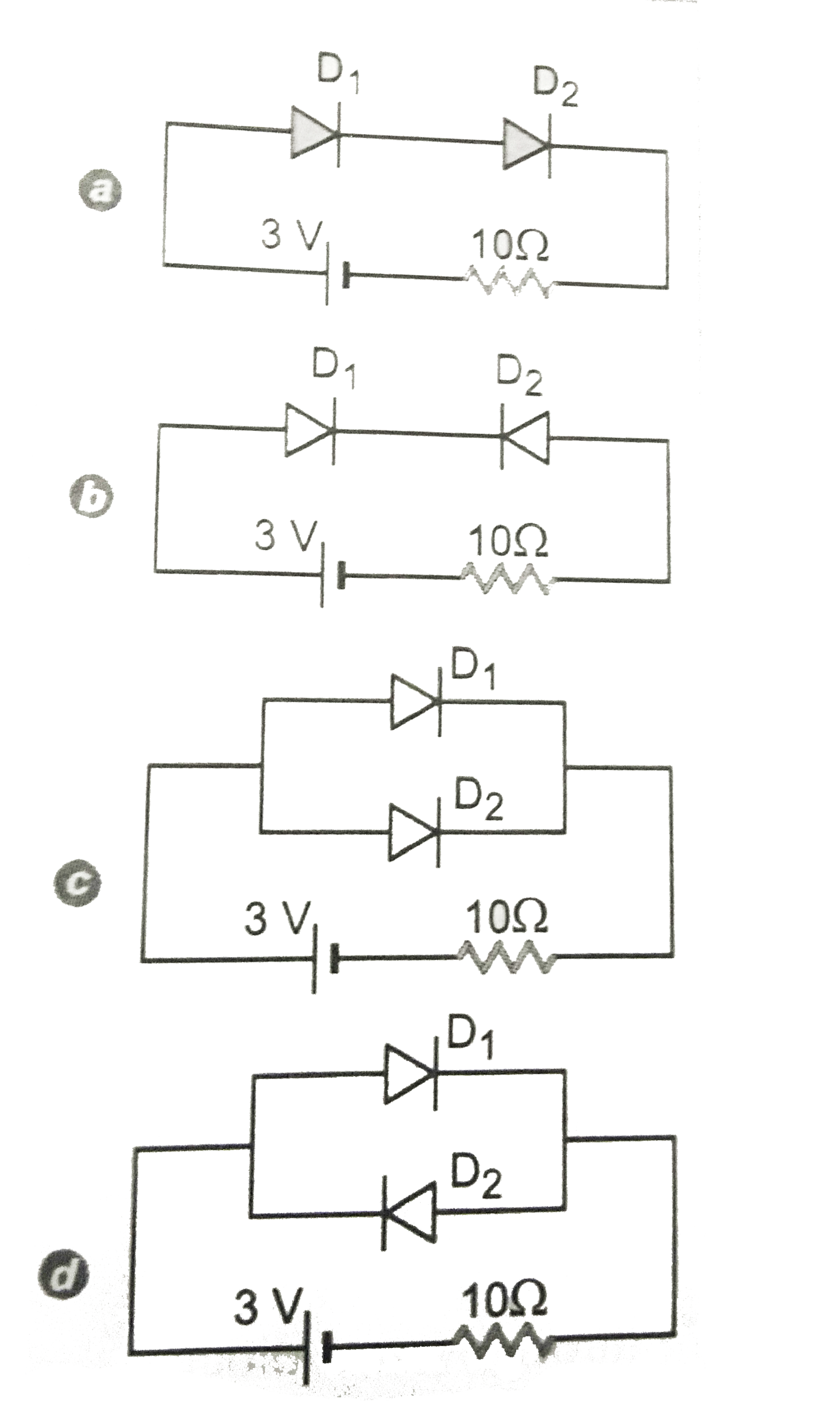
Find the total current in the circuits shown in Fig. , , and . Each diode used is ideal
Text Solution
Verified by Experts
In Fig. , both the diode `D_(1)` and `D_(2)` are forward biased. Their effective resistance in current is zero. Current in circuit is `I=3.0/10=0.3A` In Fig., diode `D_(1)` is forward bias and diode `D_(2)` is reverse biased. Resistance due to `D_(2)` will be infinity to the current flowing through it. So Current in the circuit, `I=(3.0)/(10+oo)=0` In Fig. , both the diode `D_(1)` and `D_(2)` are forward biased, Their effective resistance in the circuit is zero. So Current in the circuit is `I=3.0/10=0.3A` In Fig. , diode `D_(1)` is forward biased and diode `D_(2)` is reverse biased. No current will flow through `D_(2)` as its resistance become infinity being reverse biased. The resistance to current by `D_(1)` is zero. The current in the circuit is due to `D_(1)` only, which is given by `I=3.0/10=0.3A`
Topper's Solved these Questions
ELECTRONIC DEVICES
PRADEEP|Exercise SAMPLE PROBLEM|2 Videos
ELECTRONIC DEVICES
PRADEEP|Exercise CONCEPTUAL PROBLEMS|1 Videos
ELECTROMAGNETIC WAVES
PRADEEP|Exercise II Focus multiple choice question|5 Videos
ELECTROSTATICS
PRADEEP|Exercise ASSERTION-REASON TYPE QUESTIONS|2 Videos
Similar Questions
Explore conceptually related problems
In the diode circuit shown in figure,
Find the current in each resistor in the circuit as shown in fig.
Find the maximum voltage across AB in the circuit shown in Fig. Assume that diode is ideal. .
Find the charge of each capacitor in the circuit shown in Fig.
Determine the current through the resistancees of the circuit shown in Fig.. The each p-n junction used is ideal one.
Find the current in each resistor in the circuit shown below:
In the circuit shown in fig.. Time constant and steady state current will be