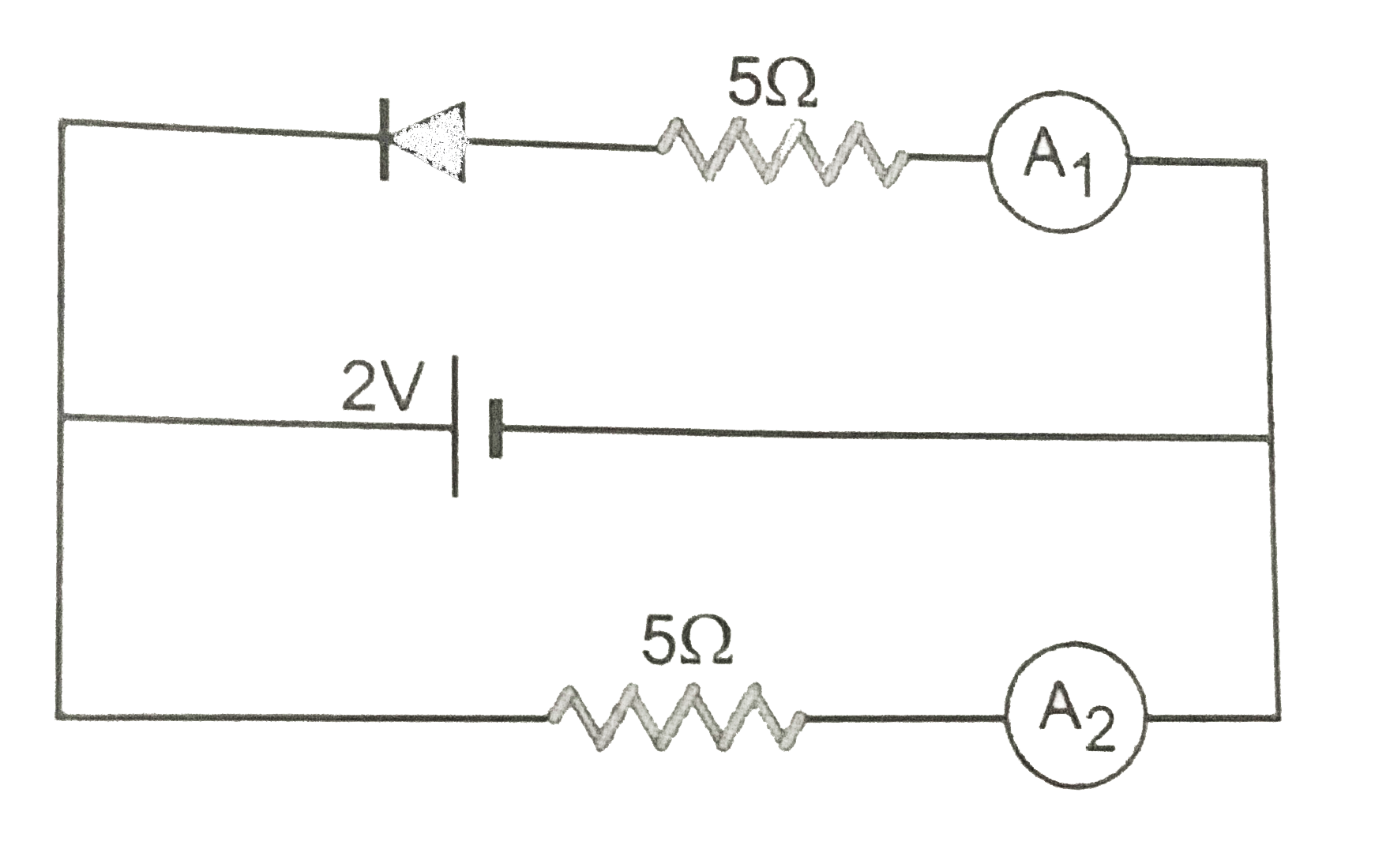
What are the reading of ammeters `A_(1)` and `A_(2)` shown in Fig.? Neglect the resistances of the ammeters, when the p-n junction used is ideal one.
Text Solution
Verified by Experts
Here the p-n junction is reversed biased with battery of emf 2V. Hence resistance of p-n junction becomes infinite. No current flows through ammeter `A_(1)`. So the reading of ammeter `A_(1)` is zero. The current through ammeter `A_(2)=2/5=0.4A`
Topper's Solved these Questions
ELECTRONIC DEVICES
PRADEEP|Exercise SAMPLE PROBLEM|2 Videos
ELECTRONIC DEVICES
PRADEEP|Exercise CONCEPTUAL PROBLEMS|1 Videos
ELECTROMAGNETIC WAVES
PRADEEP|Exercise II Focus multiple choice question|5 Videos
ELECTROSTATICS
PRADEEP|Exercise ASSERTION-REASON TYPE QUESTIONS|2 Videos
Similar Questions
Explore conceptually related problems
What are the readint of the ammeters A_(1) and A_(2) shown in figure. Neglect the resistance of the maters.
(a) What are the readings of the ammeters A_(1) and A_(2) shown in the figure.neglect the resistance of the meters. (b) Calculate the current through the circuit and the potential difference across the diode shown in the figure. The drift current fo the diode is 20muA . (c ) Each of the resistances shown in the figure has a value of 20Omega . find the equivalent resistance between A and B . Does it depend on whether the point A or B is at higher potential?
If the reading of ammeter A_(3) in figure is 0.75 A. Neglecting the resistances of the ammeters, the reading of ammeter A_(2) will be :
Determine the current through the resistancees of the circuit shown in Fig.. The each p-n junction used is ideal one.
If the reading of ammeter A_(1) in figure is 2.4 A, what will the ammeter A_(2) and A_(3) read? Neglect the resistances of the ammeter.
In the figure shown the readings of the ammeters A_(1) and A_(2) are respectively.
What is the reading of ammeter shown in the figure below ?
Find the equivalent resistance of the network shown in Fig.1 between the point p and Q, when the p-n junction diode used ideal one.
Find the reading of the ammeters A_(1) (in ampere) connected as shows in the network .
Find the reading of ammeter A and voltmeter V shown in the figure assuming the instruments to be ideal