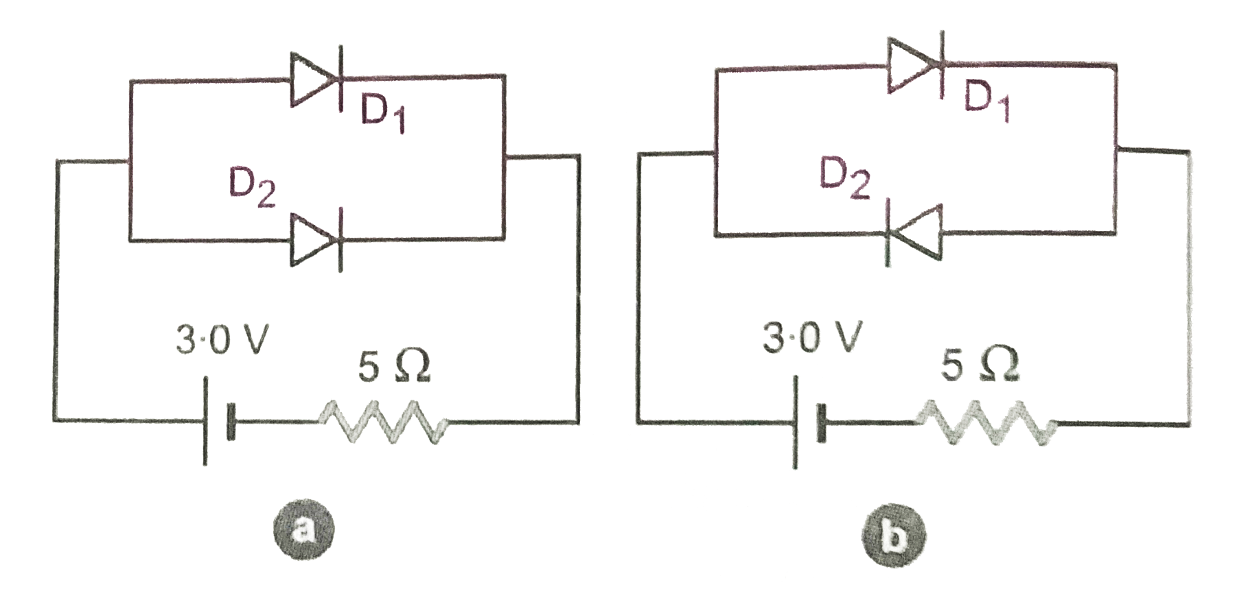
Determine the current through the resistancees of the circuit shown in Fig.. The each p-n junction used is ideal one.
Text Solution
Verified by Experts
In Fig., junction diode, `D_(1)` and `D_(2)` are forward biased and offer zero resistance. Current in the circuit, `I=3.0/5=0.6A` In Fig, junction diode, `D_(1)` is forward biased, its resistance in circuit is zero. Junction diode `D_(2)` is reverse biased, its resistance is infinity. Therefore, current in remaining circuit, `I^(')=3.0/5=0.6A`
Topper's Solved these Questions
ELECTRONIC DEVICES
PRADEEP|Exercise SAMPLE PROBLEM|2 Videos
ELECTRONIC DEVICES
PRADEEP|Exercise CONCEPTUAL PROBLEMS|1 Videos
ELECTROMAGNETIC WAVES
PRADEEP|Exercise II Focus multiple choice question|5 Videos
ELECTROSTATICS
PRADEEP|Exercise ASSERTION-REASON TYPE QUESTIONS|2 Videos
Similar Questions
Explore conceptually related problems
Determine the currents through the resistance of the circuits shown in fig.
Determine the current through the resistor for following circuits
The current through the battery shown in the circuit is
Find the current in each resistor in the circuit as shown in fig.
Find the total current in the circuits shown in Fig. , , and . Each diode used is ideal
Determine the current in each branch of the network shown in Fig. 3.24
The current through the ideal diode as shown in the is
Calculate the current shown by the ammeter A in the circuit shown in Fig. 4.47.
The current through the 8Omega resistor (shown in fig.) is
In the circuit shown in figure the current through