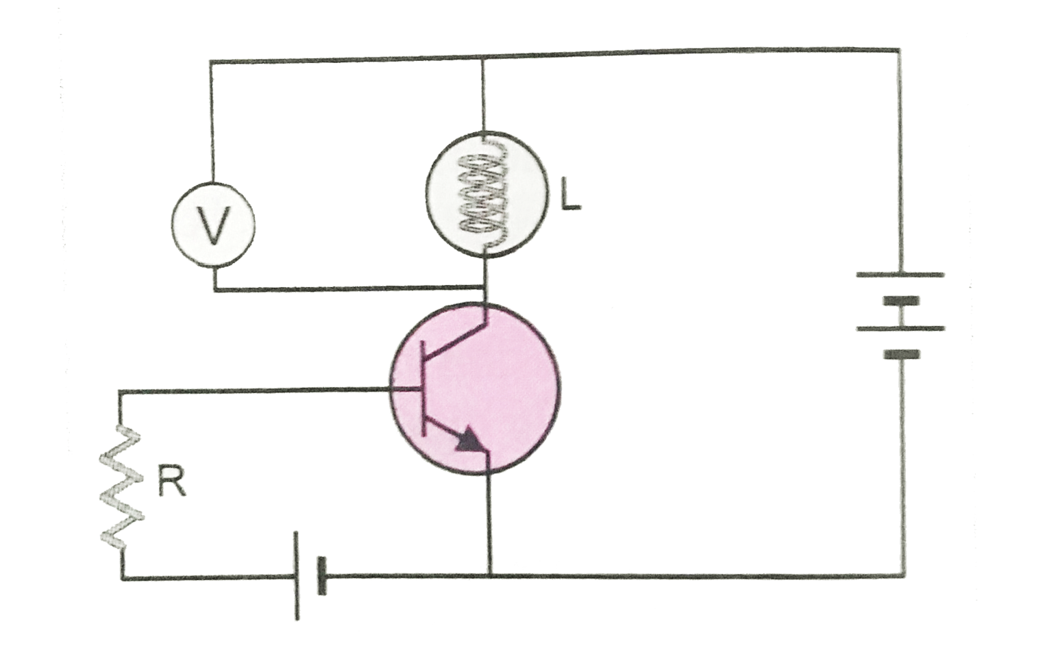
In the circuit shown in Fig.a voltage V is connected across lamp L. What changes would occur at lamp and the voltage V, if the resistance R is reduced in value?
Text Solution
Verified by Experts
Here emitter base junction of npn transistor is forward biased with a battery and resistance R. If value of R is reduced, then the current in the input circuit increases and hence emitter current `I_(e)` increases. Therefore the collector current `I_c=I_(e)-I_b` will also increase. Due to it the bulb will glow more brillantly. voltage V measures the potential difference across lamp L. Due to increase in collector current, the potential difference across L increases, hence the reading of voltage will increase.
Topper's Solved these Questions
ELECTRONIC DEVICES
PRADEEP|Exercise SAMPLE PROBLEM|2 Videos
ELECTRONIC DEVICES
PRADEEP|Exercise CONCEPTUAL PROBLEMS|1 Videos
ELECTROMAGNETIC WAVES
PRADEEP|Exercise II Focus multiple choice question|5 Videos
ELECTROSTATICS
PRADEEP|Exercise ASSERTION-REASON TYPE QUESTIONS|2 Videos
Similar Questions
Explore conceptually related problems
In the following circuit, a voltmeter V is connected across a lamp L . What change would occure in voltmeter reading if the resistance R is reduced in value?
In a common emitter transistor circuit, a bulb B and a volmeter V are connected as shown in Fig.What change would take place in bulb B and volmeter V when the value of resistance R is increased?
In the circuit shown in Fig. If both the lamps L_(1) and L_(2) are identical.
In the given circuit diagram, a voltmeter 'V' is connected across a lamp 'L'. How would (i) the brightness of the lamp and (ii) voltmeter reading 'V' be affected, if the value of resistance 'R' is decreased ? Justify your answer.
An amplifier is represented by the circuit shown in Fig. Here r_(i) is the input resistance of the amplifier and the voltage V_(i) is appearing across it. This voltage is amplified by a factor A_(V) and appears across the load as voltage V_(0) An external voltage V_(s) is applied at the input terminals of the amplifier via series resistance R_(S) . What will be the apparent gain A_(V)(=V_(0)//V_(s)) of the ampilifier in terms of A_(V), R_(S) and r_(i).
In the a.c. circuit shown in fig, the main supply hs constant voltage but variable frequency. For what frequency will the voltage across the resistance R be maximum ?
A sinusoidal voltage of rms value 200 volt is connected to a diode and a resistor R in the circuit as shown in Fig., so that half wave rectification occurs. If the diode is ideal, what is the rms voltage across R? If resistor R is replaced by capactior of capacitance C, find the potential difference across C.
In a series C-R circuit shown in figureure, the applied voltage is 10 V and the voltage across capacitor is found to 8 V . The voltage across R , and the phase difference between current and the applied voltage will respectively be .
The series L–C–R circuit shown in fig. is in resonance state. What is the voltage across the inductor?
In a series CR circuit shown in figure,the applied voltage is 10V and the voltage across capacitor is found to be 8V