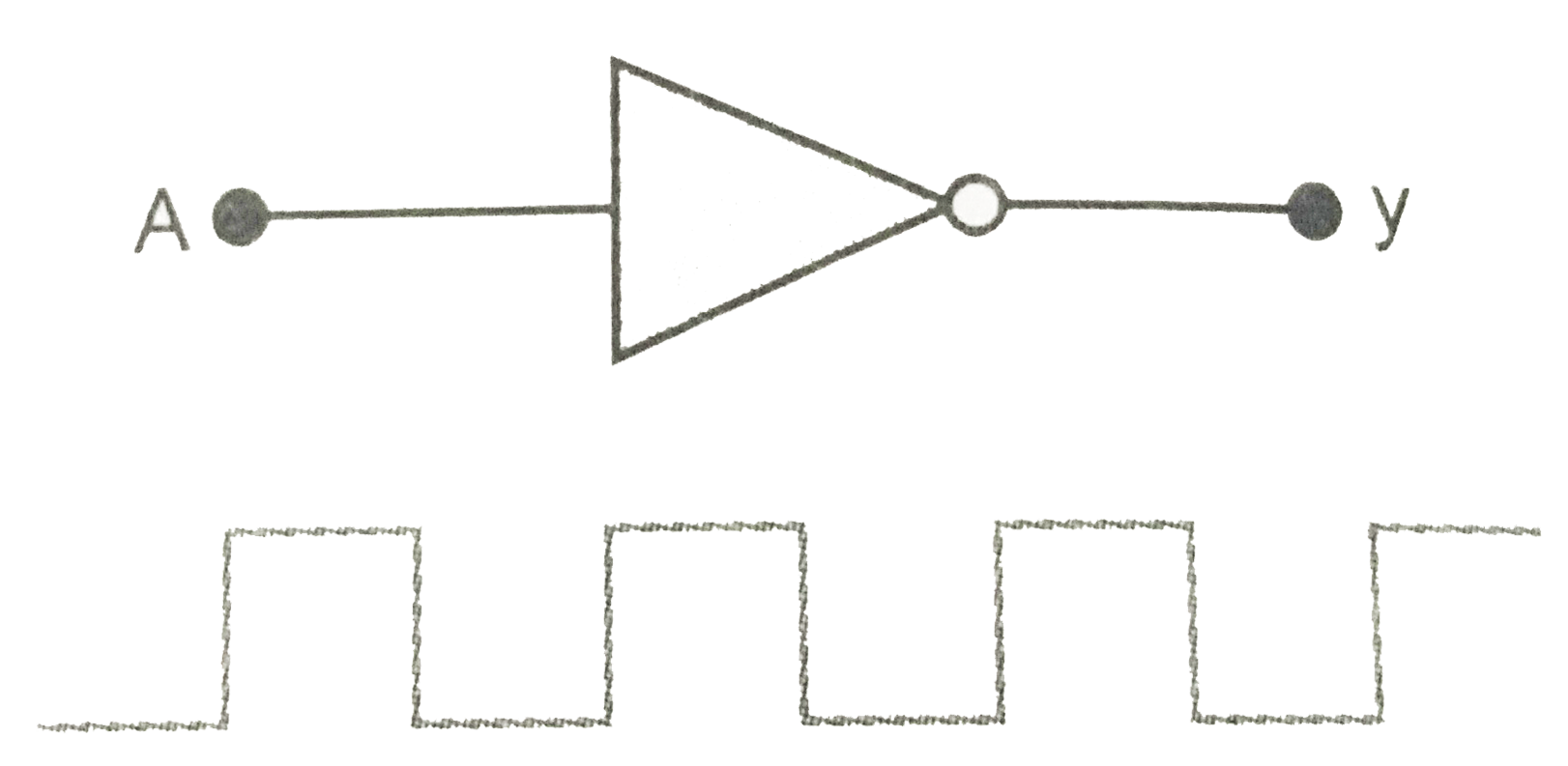
In Fig., circuit of a logic gate and input waveform is shown. (i) Name the logic gate (ii) Write its truth table and (iii) give the output wavefrom.
Text Solution
Verified by Experts
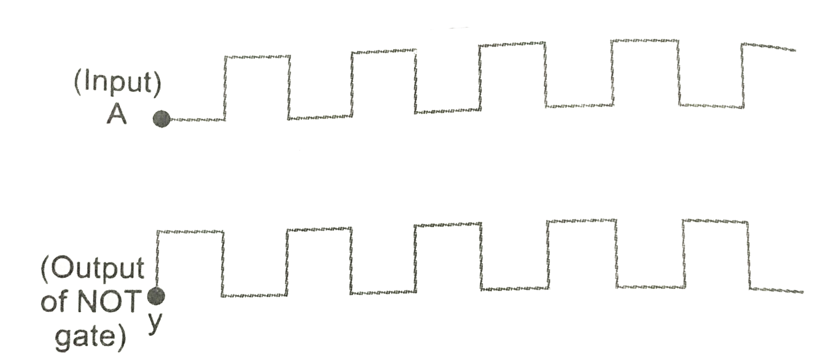
(i) The name of the logic gate is NOT gate. (ii) Boolean expression of NOT gate is, `y=barA` Thus truth table of NOT gate is show here. `|{:(A,y),(0,1),(1,0):}|` (iii) The output waveform for the NOT gate will inverse the shap show below
Topper's Solved these Questions
ELECTRONIC DEVICES
PRADEEP|Exercise SAMPLE PROBLEM|2 Videos
ELECTRONIC DEVICES
PRADEEP|Exercise CONCEPTUAL PROBLEMS|1 Videos
ELECTROMAGNETIC WAVES
PRADEEP|Exercise II Focus multiple choice question|5 Videos
ELECTROSTATICS
PRADEEP|Exercise ASSERTION-REASON TYPE QUESTIONS|2 Videos
Similar Questions
Explore conceptually related problems
For given logic gate circuit, which truth table is right.
The truth table of a logic gate is a table
For given logic gate truth table is
Draw the logic symbol of NAND gate and give its Truth table
The logic circuit and its truth table are given, what is the gate X in the diagram .
What is a logic gate name the logic gate obtained from the figure and write its truth table
The Fig.shows a logic gate circuit with two inputs A and B and the output C are as shown in Fig.
Write the truth table for the circuit shown in name the gate that the circuit resembles