Home
Class 12
PHYSICS
Identify the logic gates marked P and Q ...

Identify the logic gates marked P and Q in the circuit Fig. Write the truth table for this combination.

Text Solution

Verified by Experts

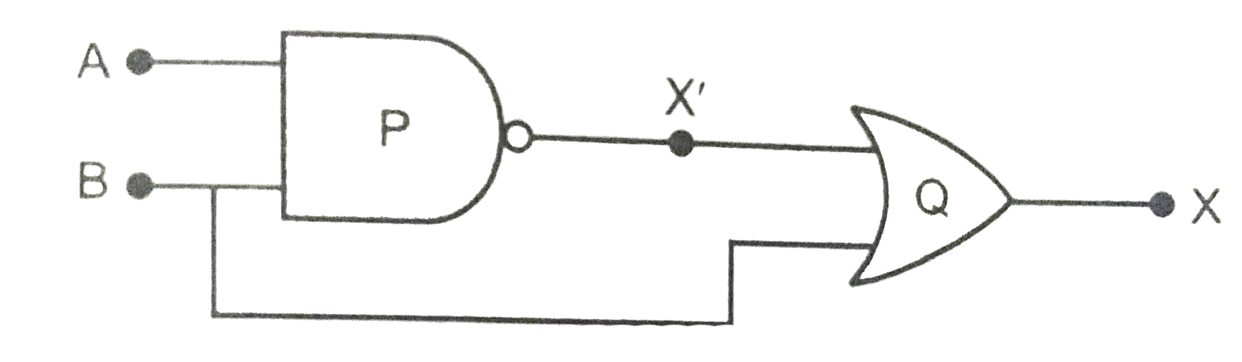
Logic gate P is NAND gate and Q is OR gate.
The Boolean expression for NAND gate is
`X^(')=bar(A.B)=barA+barB`
The Boolean expression for the combination of gates is
`X=X^(')+B=(barA+barB)+B`
`=barA+(barB+B)=barA+1 [ :' bar+B=1]`
The truth table for the combination of gates is shown below.
`|{:(A,B,barA,barB,barA+barB,X=(barA+barB)+B),(0,0,1,1,1,1),(0,1,1,0,1,1),(1,0,0,1,1,1),(1,1,0,0,0,1):}|`
It means output is always 1 whatever may be the values of inputs A and B.
Promotional Banner

Topper's Solved these Questions

  • ELECTRONIC DEVICES

    PRADEEP|Exercise SAMPLE PROBLEM|2 Videos
  • ELECTRONIC DEVICES

    PRADEEP|Exercise CONCEPTUAL PROBLEMS|1 Videos
  • ELECTROMAGNETIC WAVES

    PRADEEP|Exercise II Focus multiple choice question|5 Videos
  • ELECTROSTATICS

    PRADEEP|Exercise ASSERTION-REASON TYPE QUESTIONS|2 Videos

Similar Questions

Explore conceptually related problems

Write the truth table for the given combination of gates

Identify the logic gates marked P and Q in the given logic circuit Fig. Write down then output at X for the inputs (i) A=0,B=0 and (ii) A=1, B=1 .

Identify the logic gate markeed P and Q in the given logic circuit Fig . Write down the output at X for the inputs (i) A=0,B=0 and (ii) A=1, B=1 .

Identify the gates P and Q shown in the figure. Write the truth table for the combination of the gates shown. Name the equivalent gate representing this circuit and write its logic symbol.

(i) Identify the logic gates marked P and Q in the given logic circuit Fig. (ii) Write down the output at X for the inputs A=0, B=0 and A=1, B=1 .

(i) Identify the logic gates marked P and Q in the given logic circuit. (ii) Write down the output at X for the inputs A = 0 , B = 0 and A = 1 , B = 1.

Write the truth table of AND gate.

Identify the logic gates marked P and Q in the given logic circuit. Write down the Boolean expression for this logic circuit and truth table.

Write the truth table for the circuit shown in Fig.

Identify the logic gates marked X, Y in the given logic circuit Fig. Write down then output at y, when (i) A=0,B=0 and (ii) A=1, B=1 .