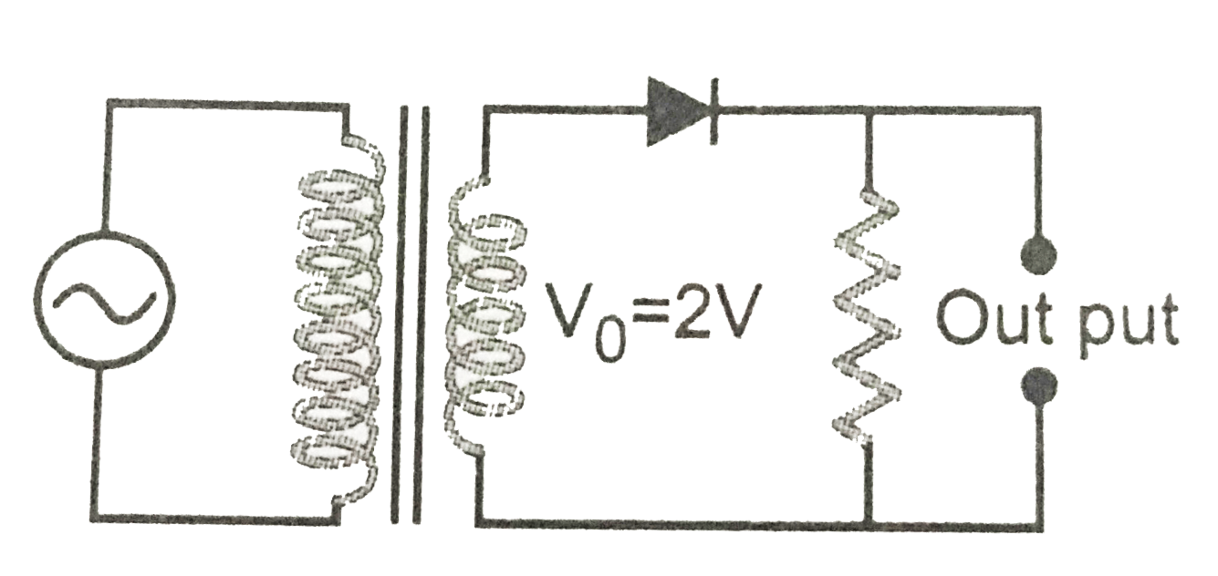
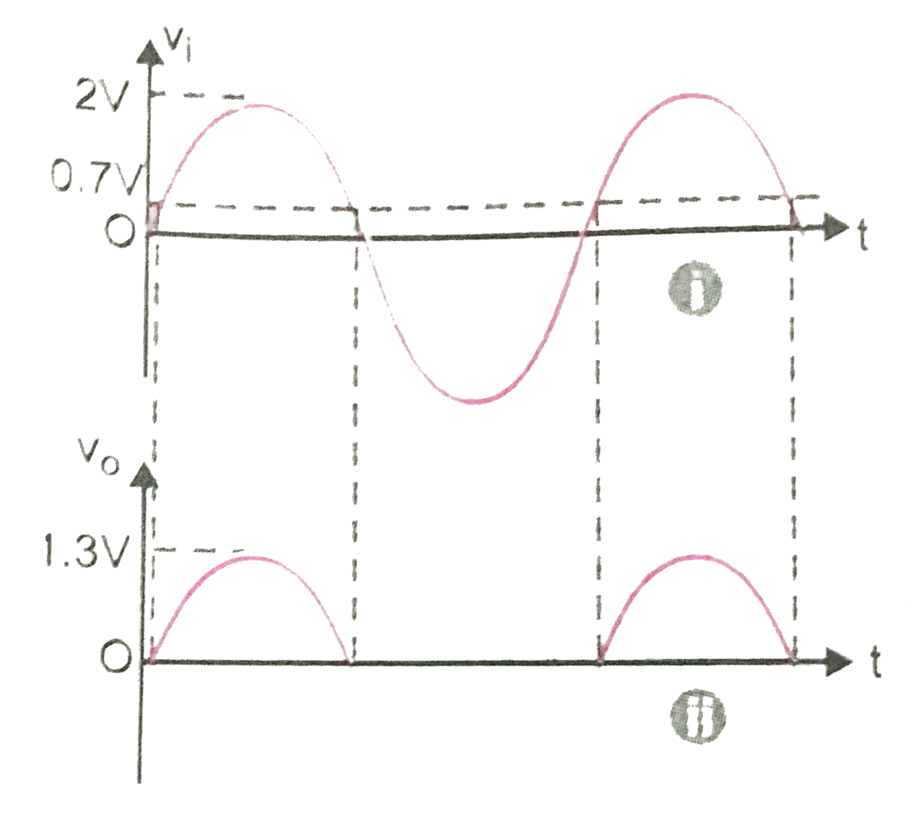
Consider the half wave rectifier circuit Fig.Assume the diode to be a silicon diode with a thershold voltage of `0.7 V`. Draw the output if the input is a sine wave with an amplitude of `2V`.
Text Solution
Verified by Experts
Since the diode threshold voltage is `0.7 V`, the diode will not conduct till the input voltage reaches from 0 to `0.7 V`. It will conduct from `0.7 V` to 2V input voltage and again till the input voltage falls down to `0.7V`. Thus, the input and output wave from for the half wave rectifier will be as shown in the Fig. (i) and (ii) respectively.
Topper's Solved these Questions
ELECTRONIC DEVICES
PRADEEP|Exercise SAMPLE PROBLEM|2 Videos
ELECTRONIC DEVICES
PRADEEP|Exercise CONCEPTUAL PROBLEMS|1 Videos
ELECTROMAGNETIC WAVES
PRADEEP|Exercise II Focus multiple choice question|5 Videos
ELECTROSTATICS
PRADEEP|Exercise ASSERTION-REASON TYPE QUESTIONS|2 Videos
Similar Questions
Explore conceptually related problems
Consider a silicon diode with a threshold voltage of -0.7V , used as a half wave rectifier. Draw the output if the input is a sine wave from of amplitude 2V and circuit is on in reverse position.
A full wave rectifier circuit along with the input and output are shown in Fig. the concentrations from the diode I is (are)
Assuming that the silicon diode having resistance of 20 Omega , the current through the diode is (knee voltage 0.7 V)
In the half-wave rectifier circuit shown. Which one of the following wave forms in true for V_(CD) , if the input is as shown?
Draw the block diagram of a simple half wave rectifier circuit with respective output wave form
The symbol of a diode is show in the figure (a) the diode is a _________rectifier diode / photo diode / zener diode (b) draw the VI characteristics of above diode (c ) a zener diode with V_(z)=6.0 V is sued for voltage regulation if the unregulated input is 10.0 V what is the value of series resistor R (d) what is the fundamental frequency of the ripple in a full wave rectifier cirucit operating from 50 Hz mains
In the given circuit a silicon diode with knee voltage 0.7V is forward biased with a battery of e.m.f 8V. The current in the circuit is 40 mA. Find the power drop at resistor R and diode.