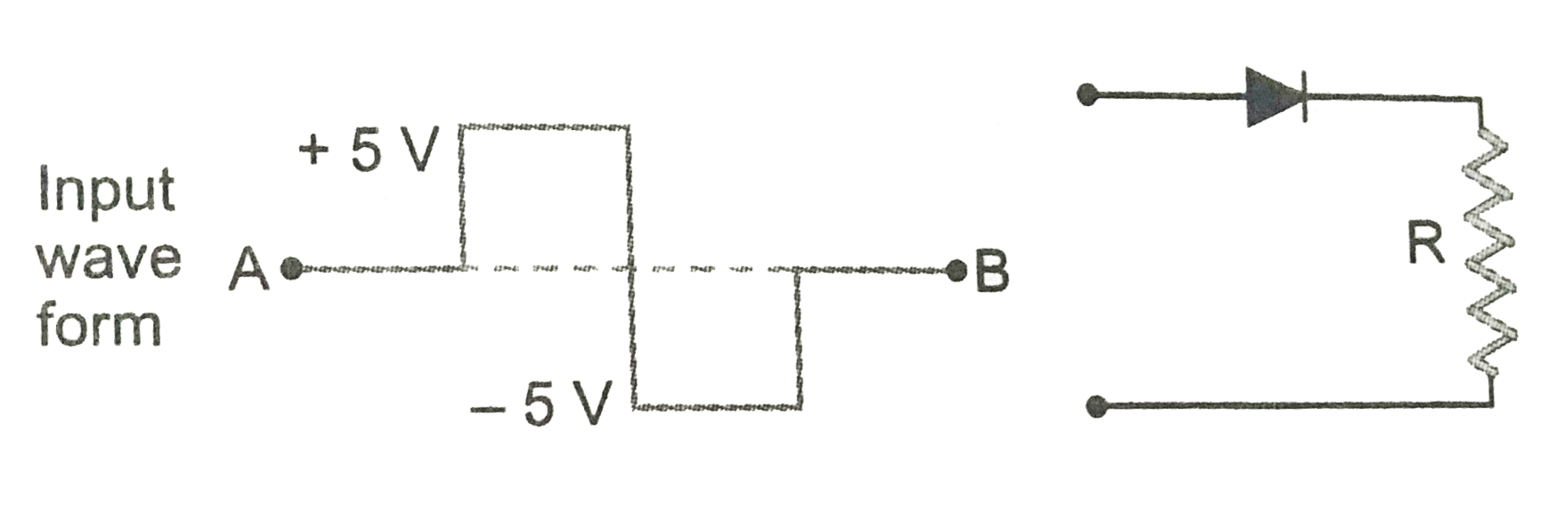
Draw and explain the output waveform across the load resistor R, if the input wave from is as shown in Fig.
Text Solution
Verified by Experts
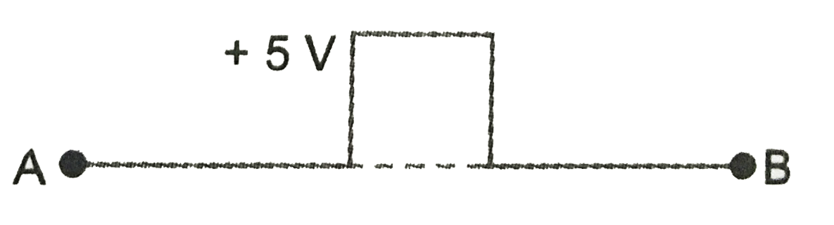
When the input voltage is `+5V`, the p-n junction diode is forward biased. The output voltage across R is `+5V`. When the input voltage is `-5V`, the p-n junction diode get reverse biased. Therefore, the output voltage across R is zero. The output wave form is as shown in Fig .
Topper's Solved these Questions
ELECTRONIC DEVICES
PRADEEP|Exercise SAMPLE PROBLEM|2 Videos
ELECTRONIC DEVICES
PRADEEP|Exercise CONCEPTUAL PROBLEMS|1 Videos
ELECTROMAGNETIC WAVES
PRADEEP|Exercise II Focus multiple choice question|5 Videos
ELECTROSTATICS
PRADEEP|Exercise ASSERTION-REASON TYPE QUESTIONS|2 Videos
Similar Questions
Explore conceptually related problems
Draw the output wave form across the resistor
Draw the output waveform across the resistor (Fig.)
What is an ideal diode ? Draw the output waveform across the load resistor R, If the wavelength is as shown in the figure.
Write the output waveform of the OR gate for the inputs
In the circuit shown in Fig. if we assume that when the input voltage at the base resistance is 5V, V_(BE) is zero and V_(CE) is also zero. What is I_,I_ and beta? When the input is zero, then I_ is zero. What would be the output wave form if the input wave form is as shown in Fig.
Show the output waveform of OR gate for the following input waveforms of A and B
Show the output waveform of OR gate for the following input waveforms of A and B
show the output waveform of AND gate for the following input waveforms of A and B.
Drawn the output waveform at X, using thye given inputs A and B for the logic circuit shown in Fig. Also identify the logic operation performed by this circuit.