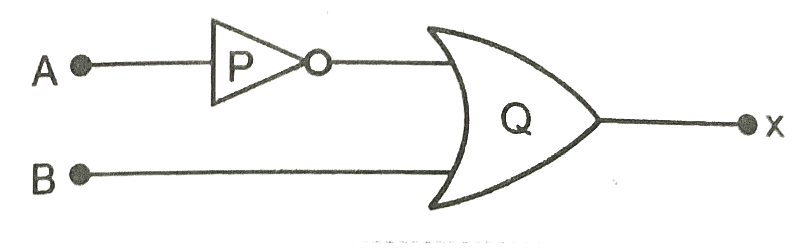
(i) Identify the logic gates marked P and Q in the given logic circuit Fig. (ii) Write down the output at X for the inputs `A=0, B=0` and `A=1, B=1`.
Text Solution
Verified by Experts
Logic gate P is NOT gate and logic gate Q is OR gate. The Boolean expression for this gate is `X=barA+B` The truth table for the given values of A and B of the above circuit is shown below. `|{:(A,barA,B,y=barA+B),(0,1,0,1),(1,0,1,1):}|`
Topper's Solved these Questions
ELECTRONIC DEVICES
PRADEEP|Exercise SAMPLE PROBLEM|2 Videos
ELECTRONIC DEVICES
PRADEEP|Exercise CONCEPTUAL PROBLEMS|1 Videos
ELECTROMAGNETIC WAVES
PRADEEP|Exercise II Focus multiple choice question|5 Videos
ELECTROSTATICS
PRADEEP|Exercise ASSERTION-REASON TYPE QUESTIONS|2 Videos
Similar Questions
Explore conceptually related problems
(i) Identify the logic gates marked P and Q in the given logic circuit. (ii) Write down the output at X for the inputs A = 0 , B = 0 and A = 1 , B = 1.
Identify the logic gates marked P and Q in the given logic circuit Fig. Write down then output at X for the inputs (i) A=0,B=0 and (ii) A=1, B=1 .
Identify the logic gate markeed P and Q in the given logic circuit Fig . Write down the output at X for the inputs (i) A=0,B=0 and (ii) A=1, B=1 .
Identify the logic gates marked X, Y in the given logic circuit Fig. Write down then output at y, when (i) A=0,B=0 and (ii) A=1, B=1 .
Identify the logic gates marked P and Q in the circuit Fig. Write the truth table for this combination.
Identify the logic gates marked P and Q in the given logic circuit. Write down the Boolean expression for this logic circuit and truth table.
Identify the logic gates marked X,Y in Fig. MTP 1.1. write down the output at y, when A=1,B=1 and A=0 and B=0.
Identify the logic gates marked X and Y in Fig.Write down the output at y, when A=1, B=1 and A=0,B=1 |{:(A,B,y',y),(1,1,0,1),(0,1,1,1):}:|
Identify the logic gate equivalent to the circuit shown in the Fig.Draw the truth table for all possible values of inputs A and B.