Home
Class 12
PHYSICS
The Fig shown input waveforms A and B to...

The Fig shown input waveforms A and B to a logic gate. Draw the output waveform for an OR gate. Write the truth table for this logic gate and draw its logic symbol.

Text Solution

Verified by Experts

The Boolean expression for OR gate is `y=A+B`. It means, the output of an OR gate will be maximum if one or more inputs will be maximum.
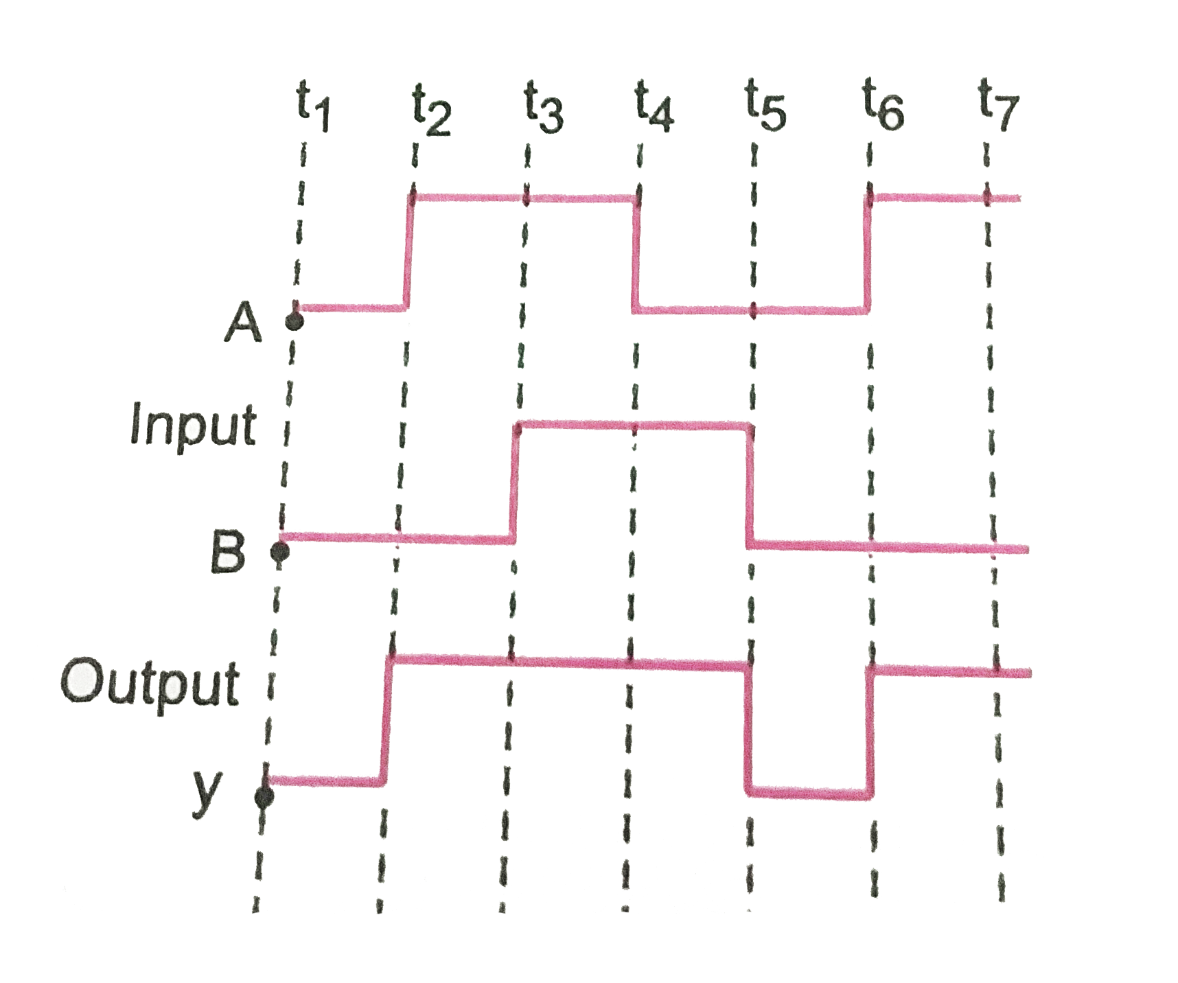
Thus the output waveform will be as showing in Fig.by curve y.
The truth table of OR gates is shown below:
`|{:(,A,B,y=A+B,),("For" t_(1)"to"t_(2),0,0,0,),("For" t_(2)"to" t_(3),1,0,1,),("For" t_(3)"to"t_(4),1,1,1,),("For" t_(4) "to" t_(5),0,1,1,),("For"t_(5) "to"t_(6),0,0,0,),("For" t_(6)"to"t_(7),1,0,0,),("For" gtt_(7),1,0,1,):}|`
Promotional Banner

Topper's Solved these Questions

  • ELECTRONIC DEVICES

    PRADEEP|Exercise SAMPLE PROBLEM|2 Videos
  • ELECTRONIC DEVICES

    PRADEEP|Exercise CONCEPTUAL PROBLEMS|1 Videos
  • ELECTROMAGNETIC WAVES

    PRADEEP|Exercise II Focus multiple choice question|5 Videos
  • ELECTROSTATICS

    PRADEEP|Exercise ASSERTION-REASON TYPE QUESTIONS|2 Videos

Similar Questions

Explore conceptually related problems

The Fig.shows the input wavwforms A and B for 'AND' gate. Draw the output waveform and write the truth table for this logic gate.

The truth table of a logic gate is a table

Write the output waveform of the OR gate for the inputs

Show the output waveform of OR gate for the following input waveforms of A and B

Show the output waveform of OR gate for the following input waveforms of A and B

Draw the truth table for the logic gate arrangement shown in the figure.

The following Fig. shows the input waveforms (A,B) and the output waveform (y) of a gate. Identify the gate and write its truth table.

Give the logic symbol for an OR gate. Draw the output wave form for input wave forms A and B for this gate.

Two input waveforms A and B shown in fig (a) are applied to an AND gate.Write the output waveform.