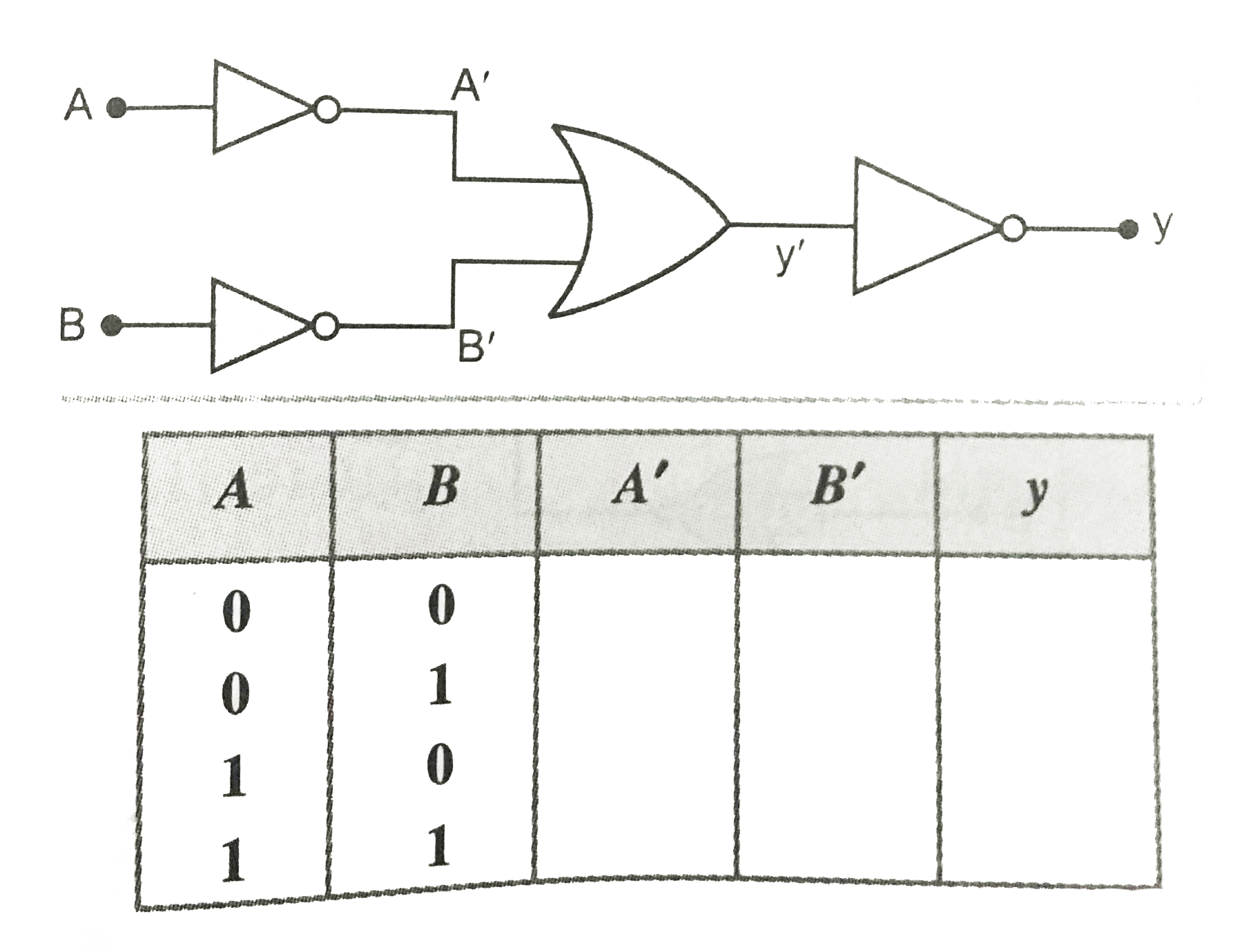
Input A and B are applied to the logic gate set up as shown in Fig.Complete the truth table given below and name the equivalent gate formed by this set up.
Text Solution
Verified by Experts
The Boolean expressions for the upper and lower NOT gates will be, `A^(')=barA` and `B^(')=barB`. Output of middle OR gate is `y^(')=A^(')+B^(')=barA+barB` Output of last NOT gate is `y=bar(y^('))=bar(barA+barB)` `=bar(barA).bar(barB)=A.B` It means the circuit is equivalent to AND gate. The complete truth table is shown below. `|{:(A,B,A'=barA,B'=barB,y=A.B),(0,0,1,1,0),(0,1,1,0,0),(1,0,0,1,0),(1,1,0,0,1):}|`
Topper's Solved these Questions
ELECTRONIC DEVICES
PRADEEP|Exercise SAMPLE PROBLEM|2 Videos
ELECTRONIC DEVICES
PRADEEP|Exercise CONCEPTUAL PROBLEMS|1 Videos
ELECTROMAGNETIC WAVES
PRADEEP|Exercise II Focus multiple choice question|5 Videos
ELECTROSTATICS
PRADEEP|Exercise ASSERTION-REASON TYPE QUESTIONS|2 Videos
Similar Questions
Explore conceptually related problems
Identify the logic gate G in the combination of gates shown in fig. The truth table is shown here
For given logic gate truth table is
To which logic gate does the truth table given below correspond ?
To which logic gate does the truth table given below correspond ?
Which logic gate corresponds to the truth table given below ?
To which logic gate does the truth table given below correspond ?
Find the output y of the logic gate whose symbol Is shown in Fig. and give a truth table for the same.
Write the truth table for the circuit shown in Fig. Name the gate so formed.