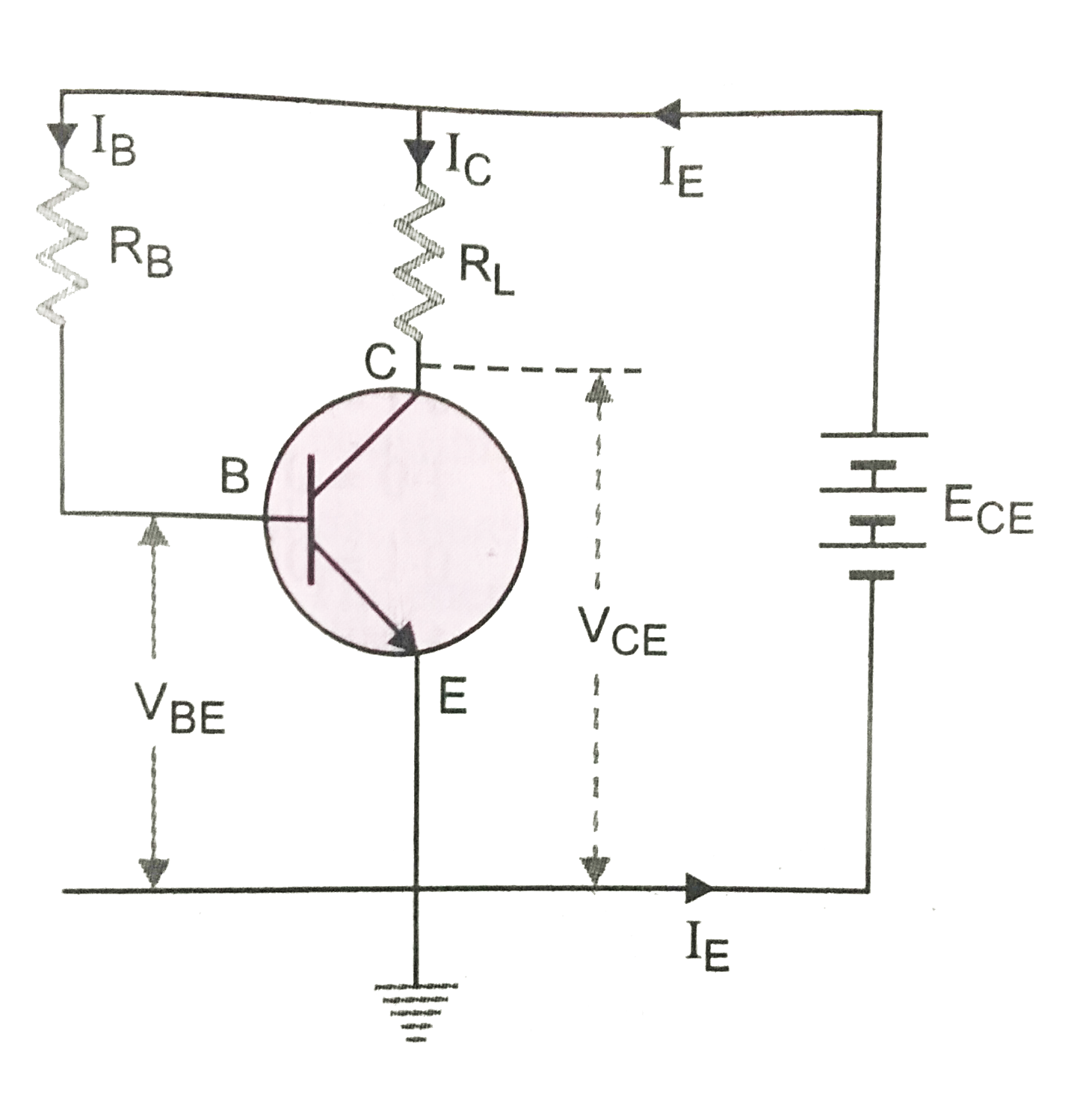
In the circuit shown in Fig. `E_(CE)=5.5V, R_(L)=1kOmega, R_=500kOmega`, the base current, `I_B` is `10muA` and collector current, `I_C=5.2mA`. Can this transistor circuit be used as an amplifier? What happens if the resistance `R_(L)` is `500Omega` and `I_B, I_C` and `R_` remain the same as above.
Text Solution
Verified by Experts
Here `E_(CE)=5.5V, R_(L)=1kOmega=10^(3)Omega` `R_B=500kOmega =500xx10^(3)Omega=5xx10^(5)Omega` `I_B=10muA=10xx10^(-6)A=10^(-5)A` `I_C=5.2xx10^(-3)A` In a battery, base-emitter circuit, we have `V_(BE)=E_(CE)-I_B R_B=5.5-10^(-5)xx(5xx10^(5))` `=0.5V` In battery, collector-emitter circuit, we have `V_(CE)=E_(CE)-I_C R_(L)=5.5-(5.2xx10^(-3))xx10^(3)` `=0.3V` Hence, `V_(BC)=V_(BE)-V_(CE)=0.5-0.3=0.2V` It shows that base becomes positive by 0.2 V with respect to collector i.e., base collector junction becomes forward biased. As both the junctions become forward biased, the circuit can not work as an amplifier. Here, `R_(L)=500Omega` `V_(CE)=5.5-(5.2xx10^(-3))xx500=2.9V` `V_(BC)=V_(BE)-V_(CE)=0.5-2.9=-2.4V` Now collector is at 2.9V w.r.t. to emitter and base is at 0.5V w.r.t. emitter. So the base collector junction is reverse biased by -2.4 V. Hence the circuit can work as an amplifier.
Topper's Solved these Questions
ELECTRONIC DEVICES
PRADEEP|Exercise SAMPLE PROBLEM|2 Videos
ELECTRONIC DEVICES
PRADEEP|Exercise CONCEPTUAL PROBLEMS|1 Videos
ELECTROMAGNETIC WAVES
PRADEEP|Exercise II Focus multiple choice question|5 Videos
ELECTROSTATICS
PRADEEP|Exercise ASSERTION-REASON TYPE QUESTIONS|2 Videos
Similar Questions
Explore conceptually related problems
In the circuit shown in figure,the base current I_(B) is 10 mu A and the collector current is 5.2 mA . The voltage ( V_(BE)) across the base and emitter is
In a transistor circuit shown here the base current is 35 muA . The value of the resistor R_(b) is
(a) For given transistor circuit, the base current is 10muA and the collector current is 5.2 mA. Can this transistor circuit be used as an amplifier. Your answer must be supported with proper explanation. (b). For a common emitter amplifier, current gain is 69. if the emitter current is 7 mA then calculate the base current and collector current.
In the circuit shown below E_(1) = 4.0 V, R_(1) = 2 Omega, E_(2) = 6.0 V, R_(2) = 4 Omega and R_(3) = 2 Omega . The current I_(1) is
In the circuit shown in adjoining fig E =10V, R_(1)=1 Omega R_(2)=2 Omega, R_(3)=3 Omega and L=2H . Calculate the value of current i_(1), i_(2) and i_(3) immidiately after key S is closed :-
The input resistance of a silicon transistor is 665Omega . Its base current is changed by 15muA which results in the change in collector current by 2mA . This transistor is used as a common emitter amplifier with a load resistance of 5kOmega . What is the voltage gain of the amplifier.