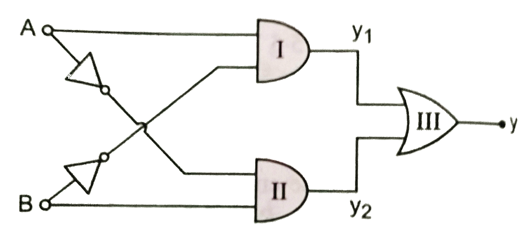
Write the truth table for the circuit shown in Fig.
Text Solution
Verified by Experts
The output of gate I (i.e., AND gate) is `y_(1)=A.barB` The output of gate II (i.e., AND gate) is `y_(2)=barA.B` The output of gate III (i.e., OR gate) is `y=y_(1)+y_(2)=A.barB+barA.B` The truth table is shown below `|{:(A,B,barA,barB,A.barB,bar.B,y=A.barB+barA.B),(0,0,1,1,0,0,0),(0,1,1,0,0,1,1),(1,0,0,1,1,0,1),(1,1,0,0,0,0,0):}|`
Topper's Solved these Questions
ELECTRONIC DEVICES
PRADEEP|Exercise SAMPLE PROBLEM|2 Videos
ELECTRONIC DEVICES
PRADEEP|Exercise CONCEPTUAL PROBLEMS|1 Videos
ELECTROMAGNETIC WAVES
PRADEEP|Exercise II Focus multiple choice question|5 Videos
ELECTROSTATICS
PRADEEP|Exercise ASSERTION-REASON TYPE QUESTIONS|2 Videos
Similar Questions
Explore conceptually related problems
Write the truth table for the circuit shown in name the gate that the circuit resembles
Write the truth table for the circuit shown in the following figure . This circuit acts like which gate ?
Write the truth table for the circuit given in Fig., consisting of NOR gates only. Identify the logic operations (OR, AND, NOT) performed by two circuits.
Write the Boolean equation and the truth table for the circuit shown in fig. Which input words does the circuit recognise?
In the circuit shown in Fig. 7.45,
Write the truth table for the logic circuit shown below and identify the logic operation performed by circuit.
The truth table for the circuit shown in the figure is
Write the truth table for circuit given in Fig.below consisting of NOR gates and identify the logic operation (OR, AND and NOT) which this circuit is performing.