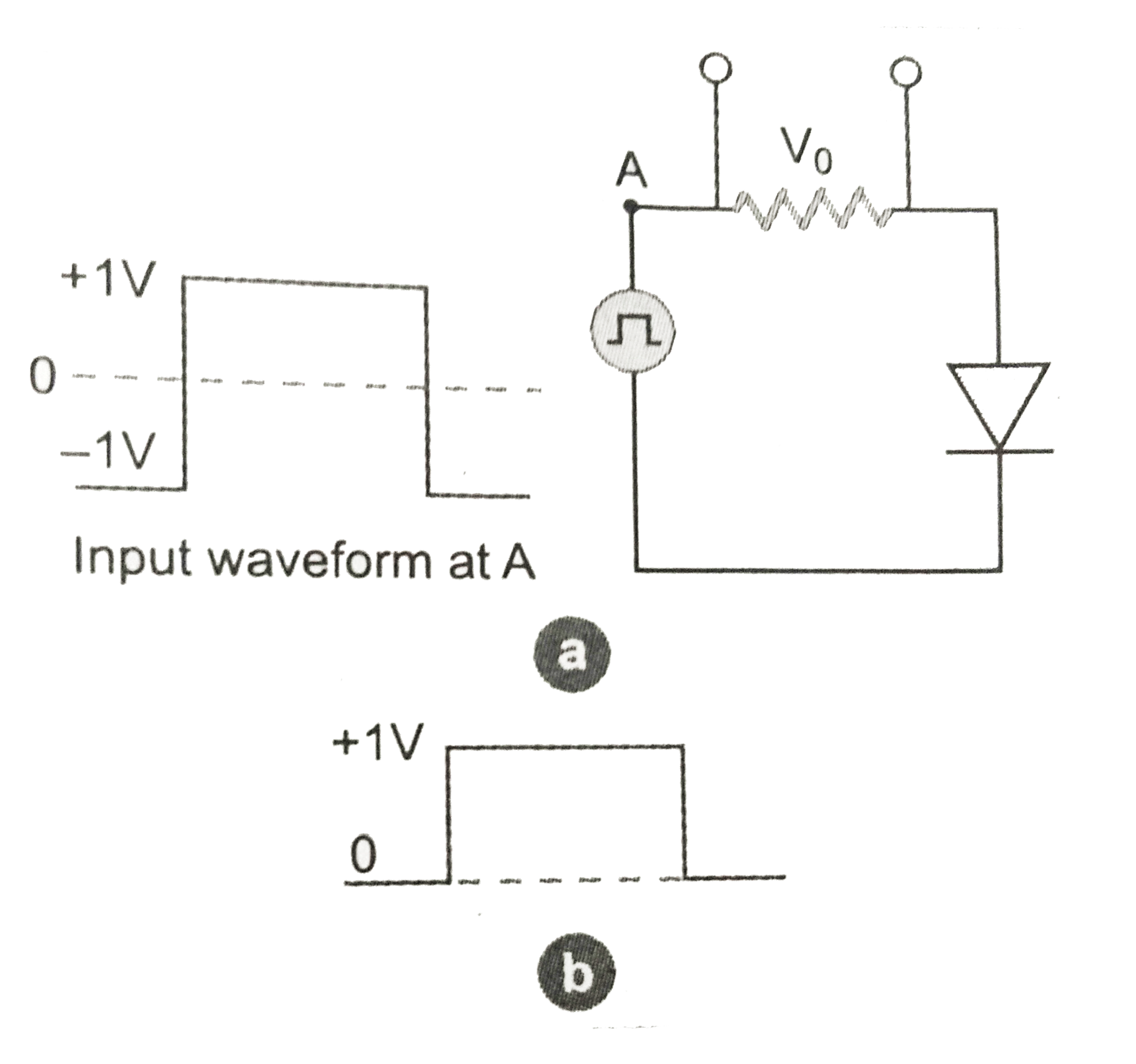
Draw the output waveform across the resistor (Fig.)
Text Solution
Verified by Experts
A p-n junction offers low resistance when forward biased and high resistance, when reverse biased. Therefore, there will be output voltage for the positive half cycle of a.c. voltage used as input. Which is shown in Fig.
Topper's Solved these Questions
ELECTRONIC DEVICES
PRADEEP|Exercise SAMPLE PROBLEM|2 Videos
ELECTRONIC DEVICES
PRADEEP|Exercise CONCEPTUAL PROBLEMS|1 Videos
ELECTROMAGNETIC WAVES
PRADEEP|Exercise II Focus multiple choice question|5 Videos
ELECTROSTATICS
PRADEEP|Exercise ASSERTION-REASON TYPE QUESTIONS|2 Videos
Similar Questions
Explore conceptually related problems
Draw the output wave form across the resistor
What is an ideal diode ? Draw the output waveform across the load resistor R, If the wavelength is as shown in the figure.
Draw and explain the output waveform across the load resistor R, if the input wave from is as shown in Fig.
Assuming the ideal diode, draw the output waveform for the circuit given in Fig.Explain the waveform.
Assuming the ideal diode, draw the output waveform for the circuit given in fig. (a), explain the waveform
(a) Draw the circuit diagram of reversed bias p-n junction. (b). Draw the output wavefrom across diode in given circuit. (c). Draw the truth table for the given logic gate.
The Fig.shows the input wavwforms A and B for 'AND' gate. Draw the output waveform and write the truth table for this logic gate.