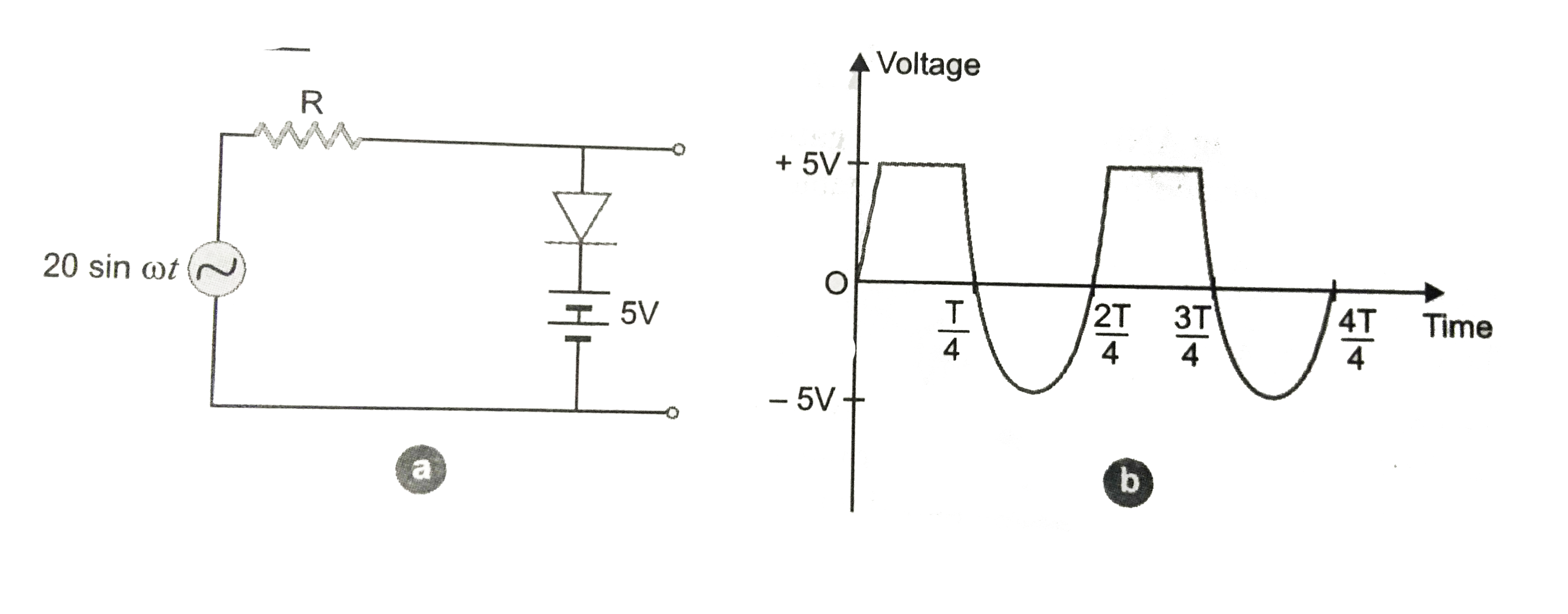
Assuming the ideal diode, draw the output waveform for the circuit given in Fig.Explain the waveform.
Text Solution
Verified by Experts
When the input voltage is equal to or less then 5V, diode will be reverse biased. It will offer high resistance in comparison to resistance (R) in series. Now diode appears in open circuit. The input wave from is then passed on to the output terminals. The result with sine wave input is to clip off all positive-going portion above `+5V` volt. If input voltage is more than `+5V`, diode will be conducting as if forward biased offering low resistance incomparison to R. But there will be no voltage in output beyond 5volt as the voltage beyond `+5V` will appear across R. When input voltage is negative, there will be opposition to 5 V battery in p-n junction circuit. Due to it, reverse bias voltage of p-n junction decreases and a voltage appears across output. When input voltage becomes more than -5V, the diode will be reverse biased. It will offer high resistance in comparison to resistance R in series. Now junction diode appears in open circuit. The input wave form is then passed on to the output terminals. The output wave form will be as shown in Fig.
Topper's Solved these Questions
ELECTRONIC DEVICES
PRADEEP|Exercise SAMPLE PROBLEM|2 Videos
ELECTRONIC DEVICES
PRADEEP|Exercise CONCEPTUAL PROBLEMS|1 Videos
ELECTROMAGNETIC WAVES
PRADEEP|Exercise II Focus multiple choice question|5 Videos
ELECTROSTATICS
PRADEEP|Exercise ASSERTION-REASON TYPE QUESTIONS|2 Videos
Similar Questions
Explore conceptually related problems
Assuming the ideal diode, draw the output waveform for the circuit given in fig. (a), explain the waveform
Draw the output waveform across the resistor (Fig.)
If the given diode is ideal, the output of the given circuit in
The output of the given circuit in Fig.
The output of the given circuit in Fig.
The output of the given circuit in Fig. .
show the output waveform of AND gate for the following input waveforms of A and B.
Write the output waveform of the OR gate for the inputs