Text Solution
Verified by Experts


Topper's Solved these Questions
ELECTRONIC DEVICES
PRADEEP|Exercise HIGHER ORDER THINKING SKILLS|1 VideosELECTRONIC DEVICES
PRADEEP|Exercise Exercise|312 VideosELECTRONIC DEVICES
PRADEEP|Exercise VERY SHORT QUESTION ANSWER (NCERT)|1 VideosELECTROMAGNETIC WAVES
PRADEEP|Exercise II Focus multiple choice question|5 VideosELECTROSTATICS
PRADEEP|Exercise ASSERTION-REASON TYPE QUESTIONS|2 Videos
Similar Questions
Explore conceptually related problems
PRADEEP-ELECTRONIC DEVICES-LONG QUESTION ANSWER (NCERT)
- Draw the output signal C(1) and C(2) in the given combination of gates...
Text Solution
|
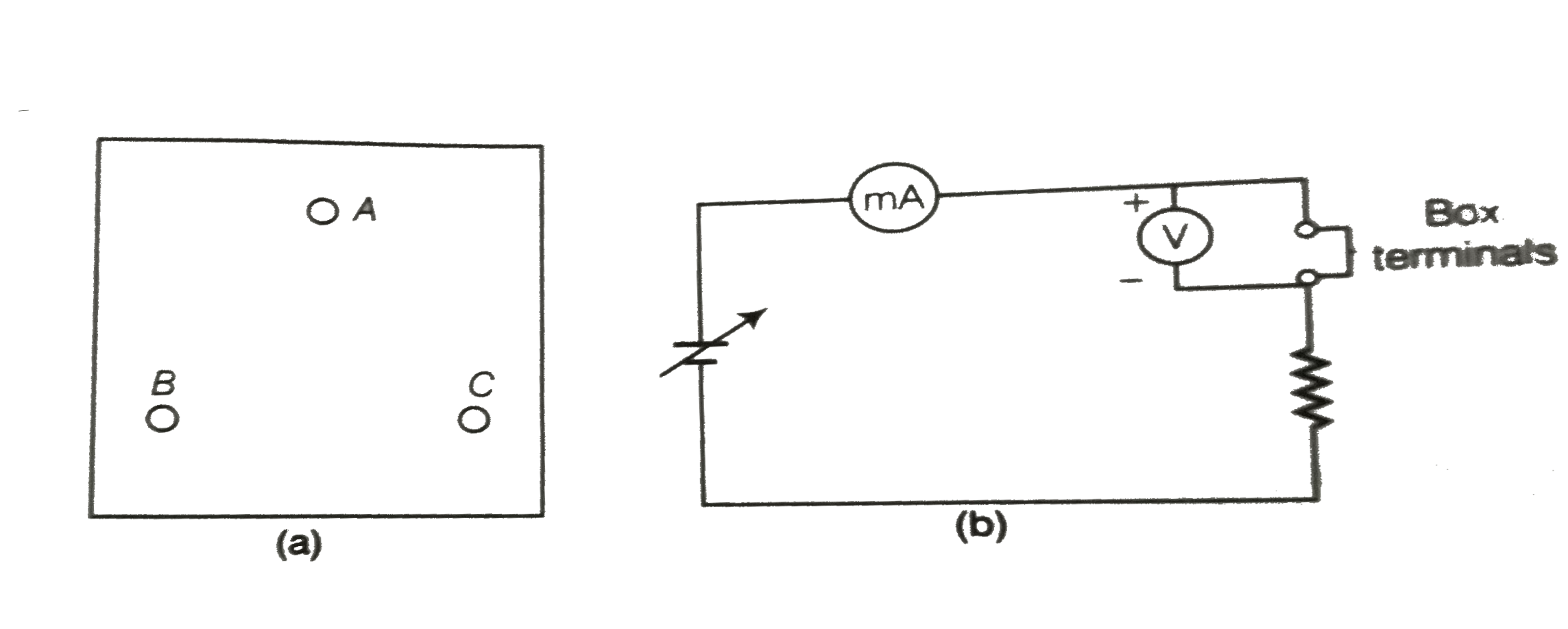
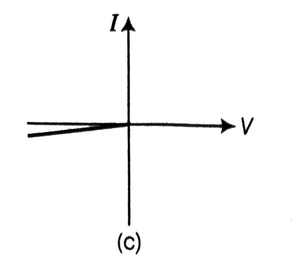
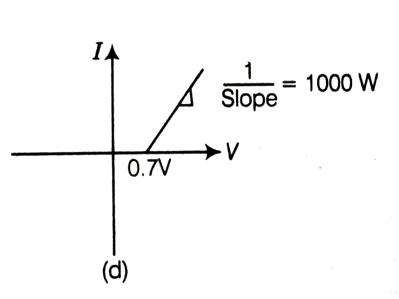
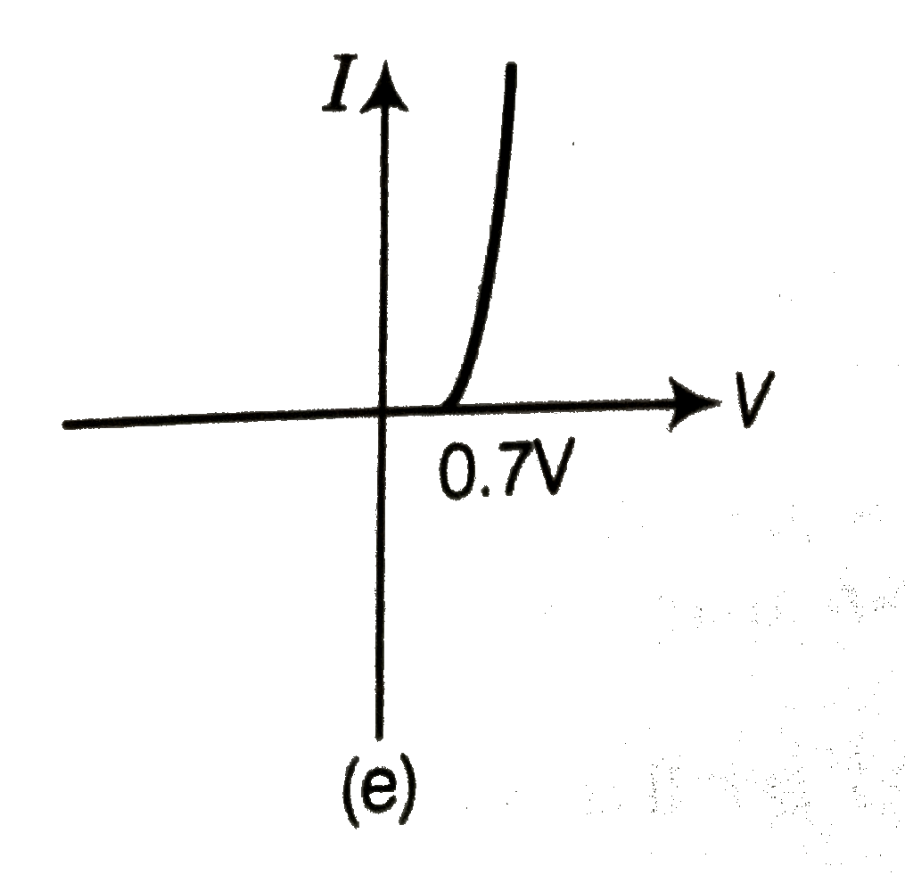
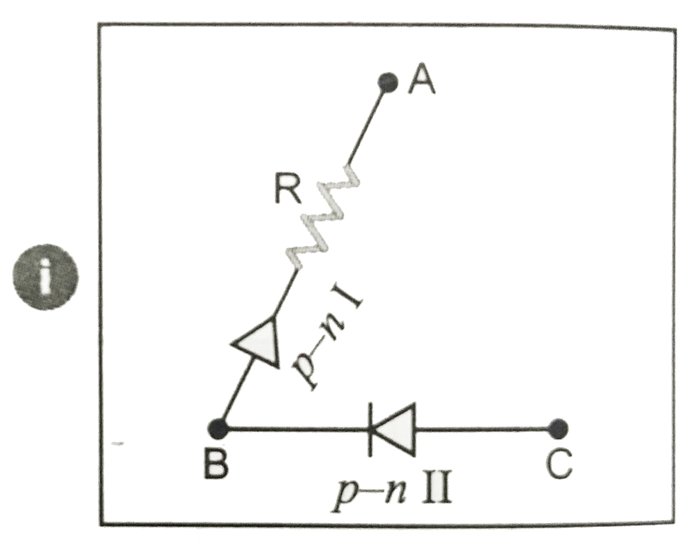
- Consider a box with three terminals on top of it as shown in figure. ...
Text Solution
|
- For the transistor circuit shown in figure , evaluate VE , RB and RE. ...
Text Solution
|
- In the circuit shown in Fig., find the value of R.
Text Solution
|