Home
Class 12
PHYSICS
The diagram Fig.12 shown a piece of pure...

The diagram Fig.12 shown a piece of pure semiconductor S in series with a variable resistor R, and a source of constant voltage V. Would you increase or decrease the value of R to keep the reading of ammeter constant, when semi-conductor S is heated? Give reason.

Text Solution

Verified by Experts

when a semiconductor is heated its resistance decreases and hence current in circuit increases. To keep the current in circuit constant, the value of resistance is to be increased.
N/A
Promotional Banner

Topper's Solved these Questions

  • ELECTRONIC DEVICES

    PRADEEP|Exercise LONG QUESTION ANSWER|2 Videos
  • ELECTRONIC DEVICES

    PRADEEP|Exercise PROBLEMS FOR PRACTICE|7 Videos
  • ELECTRONIC DEVICES

    PRADEEP|Exercise HIGHER ORDER THINKING SKILLS|1 Videos
  • ELECTROMAGNETIC WAVES

    PRADEEP|Exercise II Focus multiple choice question|5 Videos
  • ELECTROSTATICS

    PRADEEP|Exercise ASSERTION-REASON TYPE QUESTIONS|2 Videos

Similar Questions

Explore conceptually related problems

Figure shows a piece of semiconductor (pure one) S in series with a variable resistor R and a source of constant voltage V. S is heated and the current is kept constant by adjustment R . Which of the following factors will decrease during this process? (1) The drift velocity of the conduction electrons in S . (2) The DC resistance of S (3) The number of conduction electrons in S . which of the following is correct?

The time constant of an inductor is tau_(1) . When a pure resistor of R Omega is connected in series with it, the time constant is found to decrease to tau_(2) . The internal resistance of the inductor is

A constant voltage V_0 is applied to a potentiometer of resistance R connected to an ammeter. A constant resistor r is connected to the sliding contact of the potentiometer and the fixed end of the potentiometer. How will the reading of ammeter vary as the sliding contact is moved from one end of the potentiometer to the other ? The resistance of ammeter is assumed to be negligible.

In an electric iron heat producedm is same, whether it is connected across an A.c. source or across 50 V constant voltage. R.M.S. value of the A.C. voltage applied is

In the circuit shown, R=2 Omega and V = 20 volt. With switch S open the reading of ammeter is half its reading when ‘S’ is closed. Calculate the resistance of the ammeter.

The diagram shows a capacitor C and a resistor R connected in series to an AC source. V_(1) and V_(2) are voltmeters and A is ammeter Now, consider the following statemensts : (I) Reading in A and V_(2) are always in phase. (II) Reading in V_(1) is ahead in phase with reading in V_(2) , (III) Reading in A and V_(1) are always in phase. Which of these statements are/is correct

In an AC circuit as shown in the figure, the source is of r.m.s voltage 200 V and variable frequency. At resonance, the circuit

The cirucit shown in fig. extends to the right into infinity. Each battery has the electromotive force V(unknown) and the internal resistance r(known). Each resistor has the resistance 4r. The reading of the idal ammeter shown in the diagram is I. Find the value of V in terms of I and r.

PRADEEP-ELECTRONIC DEVICES-Exercise
  1. Draw a circuit diagram of a full-wave rectifier. Explain its working p...

    Text Solution

    |

  2. In the following diagram, which bulb out of B(1) and B(2) will glow an...

    Text Solution

    |

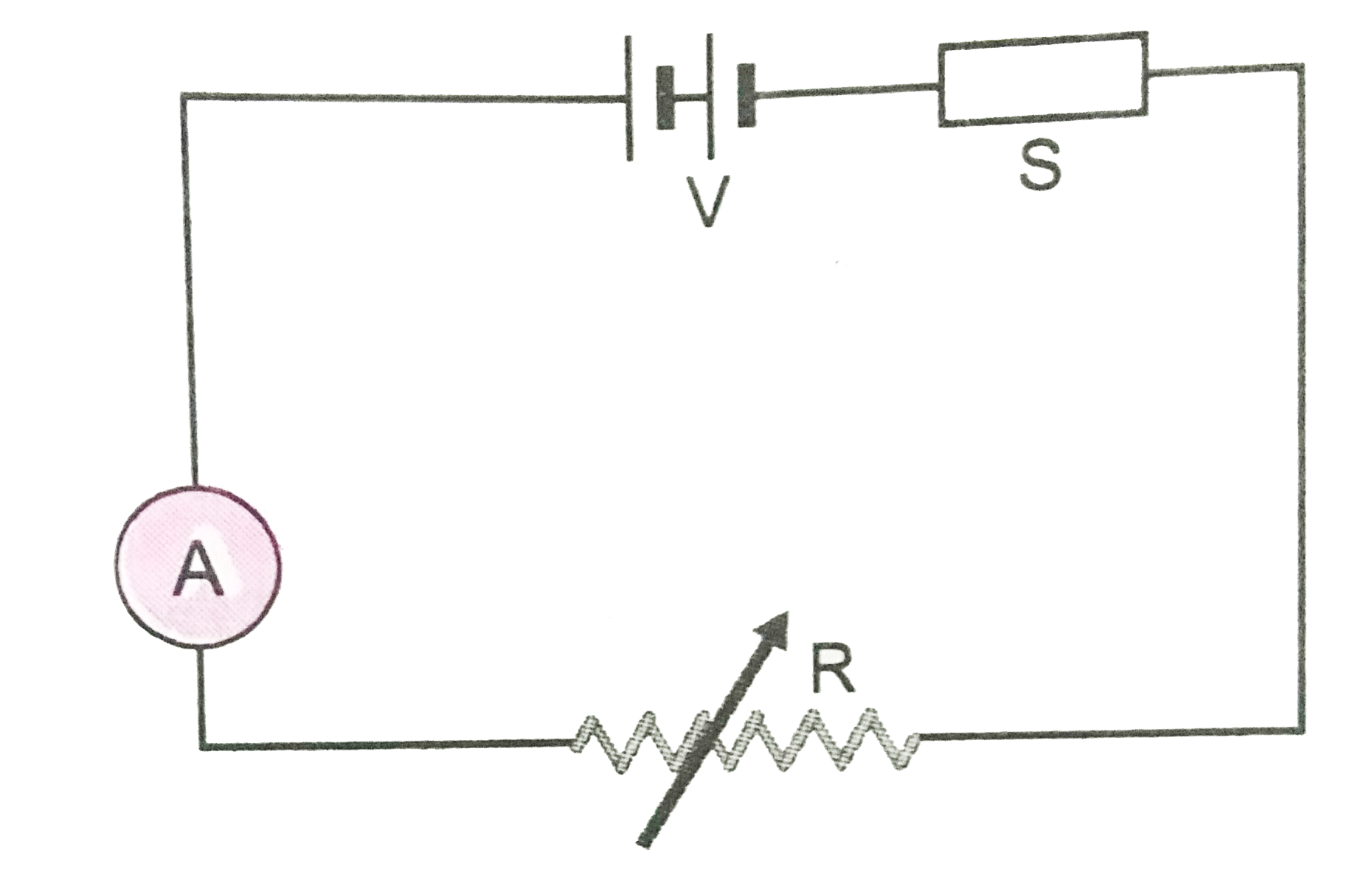
  3. The diagram Fig.12 shown a piece of pure semiconductor S in series wit...

    Text Solution

    |

  4. Draw the circuit diagram of an illuminated photodiode in reverse bias?...

    Text Solution

    |

  5. What is light emitting diode (LED) ? Mention two important advantages ...

    Text Solution

    |

  6. Mention the important considerations required while fabricating a p-n ...

    Text Solution

    |

  7. Give reasons for the following: (i) High reverse voltage do not appe...

    Text Solution

    |

  8. Write the function of three segments of a transistor.

    Text Solution

    |

  9. Sketch the three modes of study of n-p-n junction transistor.

    Text Solution

    |

  10. Explain that a transistor can be used as a switch.

    Text Solution

    |

  11. Discuss briefly the concept of an amplifier.

    Text Solution

    |

  12. Draw a circuit diagram of a transistor amplifier in CE configuration. ...

    Text Solution

    |

  13. Explain the advantages and disadvantages of semiconducting devices com...

    Text Solution

    |

  14. Give the logic symbol, truth table and Boolean expression for OR gate....

    Text Solution

    |

  15. Give the logic symbol, truth table and Boolean expression for AND gate...

    Text Solution

    |

  16. How is NOT gate realised? Explain.

    Text Solution

    |

  17. What is logic gate? Distinguish between AND and OR gates.

    Text Solution

    |

  18. What are main logic gates? How many types are they? Draw their symbols...

    Text Solution

    |

  19. Two signals A, B as given below are applied to (i) AND (ii) NOR and (i...

    Text Solution

    |

  20. Give the logic symbol, Boolean expression and truth table of NAND gate...

    Text Solution

    |