Text Solution
Verified by Experts


Topper's Solved these Questions
ELECTRONIC DEVICES
PRADEEP|Exercise LONG QUESTION ANSWER|2 VideosELECTRONIC DEVICES
PRADEEP|Exercise PROBLEMS FOR PRACTICE|7 VideosELECTRONIC DEVICES
PRADEEP|Exercise HIGHER ORDER THINKING SKILLS|1 VideosELECTROMAGNETIC WAVES
PRADEEP|Exercise II Focus multiple choice question|5 VideosELECTROSTATICS
PRADEEP|Exercise ASSERTION-REASON TYPE QUESTIONS|2 Videos
Similar Questions
Explore conceptually related problems
PRADEEP-ELECTRONIC DEVICES-Exercise
- Find output y in the folowing circuit Fig. .
Text Solution
|
- Name the 2-input logic gate, whose truth table is given here, If this ...
Text Solution
|
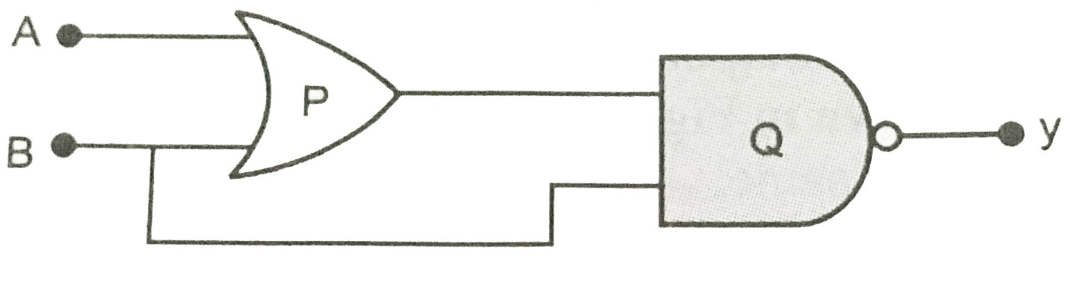
- Identify the logic gates marked P and Q in the given logic circuit. Wr...
Text Solution
|
- Identify the logic gates marked X and Y in Fig.Write down the output a...
Text Solution
|
- Two signals A, and B shown in Fig. are used as two inputs of an AND ga...
Text Solution
|
- Two signal A and B shown in the Fig. are used as two inputs of a NAND ...
Text Solution
|
- Construct a proper combination of 3 NOT and one AND gates in order to ...
Text Solution
|
- Identify the gate represented by the block diagram of Fig. Write its b...
Text Solution
|
- Write the truth table for the circuit shown in Fig. Name the gate so f...
Text Solution
|
- Input signal A and B are applied to the input terminals of the 'dotted...
Text Solution
|
- Find the binary numbers of (32.25)(10) and (24.25)(10) and give subtra...
Text Solution
|
- The conductivity of a semiconductor increases with increase in tempera...
Text Solution
|
- In Fig . V(0) is the potential barrier across a p-n junction, when no ...
Text Solution
|
- In Fig.assuming the diode to be ideal
Text Solution
|
- A 220 V AC supply is connected between points A and B . What will be t...
Text Solution
|
- Hole is
Text Solution
|
- The output of the given circuit in Fig.
Text Solution
|
- In the circuit shown(Fig.) if the diode forward voltage drop is 0.3 V,...
Text Solution
|
- Truth table for the given circuit (Fig.)is
Text Solution
|
- When an electric field is applied across a semiconductor,
Text Solution
|