A
B
C
D
Text Solution
Verified by Experts
The correct Answer is:


Topper's Solved these Questions
ELECTRONIC DEVICES
PRADEEP|Exercise LONG QUESTION ANSWER|2 VideosELECTRONIC DEVICES
PRADEEP|Exercise PROBLEMS FOR PRACTICE|7 VideosELECTRONIC DEVICES
PRADEEP|Exercise HIGHER ORDER THINKING SKILLS|1 VideosELECTROMAGNETIC WAVES
PRADEEP|Exercise II Focus multiple choice question|5 VideosELECTROSTATICS
PRADEEP|Exercise ASSERTION-REASON TYPE QUESTIONS|2 Videos
Similar Questions
Explore conceptually related problems
PRADEEP-ELECTRONIC DEVICES-Exercise
- A 220 V AC supply is connected between points A and B . What will be t...
Text Solution
|
- Hole is
Text Solution
|
- The output of the given circuit in Fig.
Text Solution
|
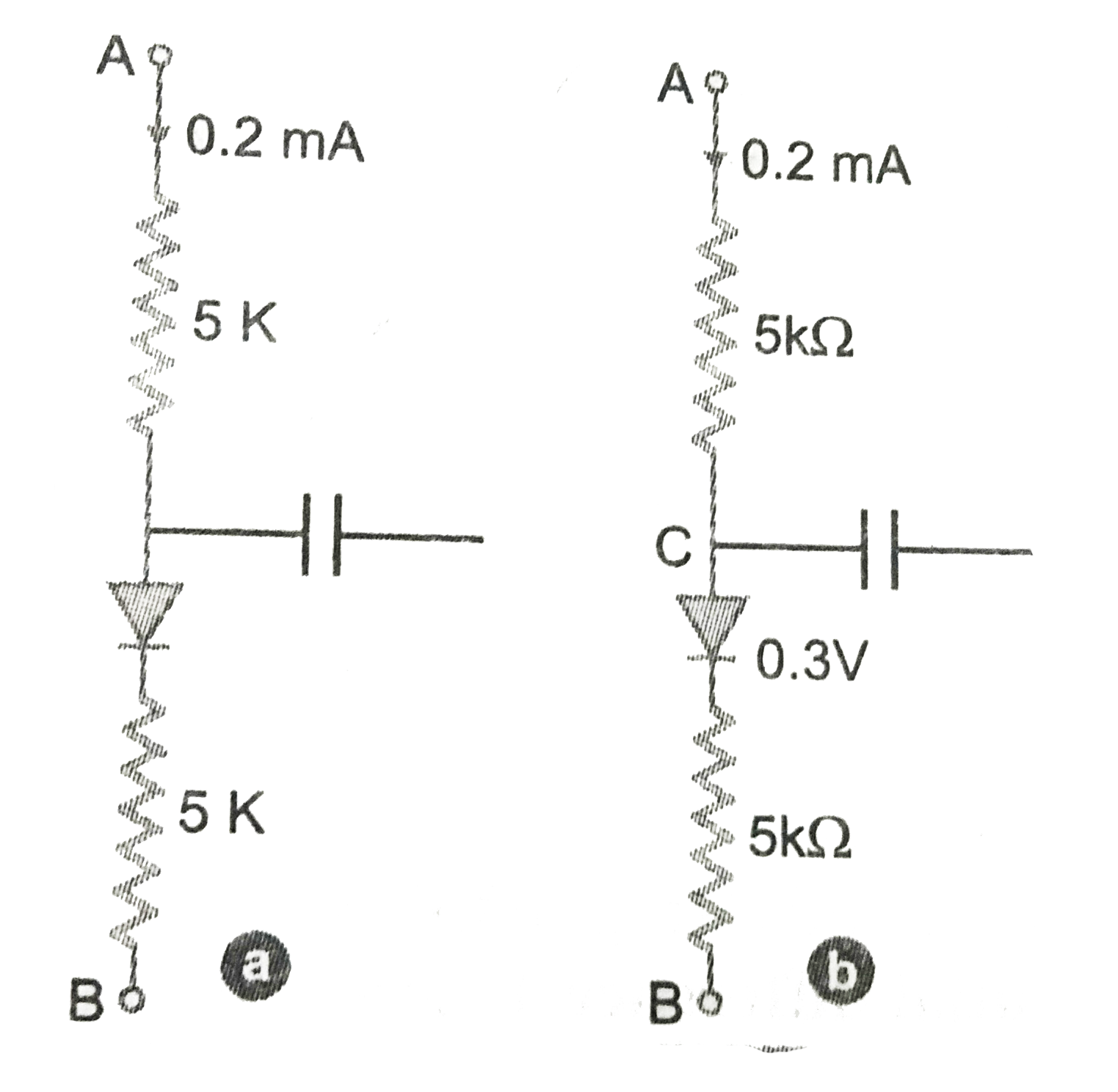
- In the circuit shown(Fig.) if the diode forward voltage drop is 0.3 V,...
Text Solution
|
- Truth table for the given circuit (Fig.)is
Text Solution
|
- When an electric field is applied across a semiconductor,
Text Solution
|
- Consider an n-p-n transistor with its base - emitter junction forward ...
Text Solution
|
- Fig.shows that transfer characteristics of a base biased CE transistor...
Text Solution
|
- In an n-p-n transistor circuit , the collector currents is 10mA . If 9...
Text Solution
|
- In the depletion region of a diode.
Text Solution
|
- What happens during regualtion action of a Zener diode?
Text Solution
|
- To reduce the ripples in rectifier circuit with capacitor filter
Text Solution
|
- The breakdown in a reverse biased p-n junction diode is more likely to...
Text Solution
|
- The resistance of an intrisic semiconductor when heated
Text Solution
|
- The electrical conductivity of a semiconductor increases when electrom...
Text Solution
|
- Which one of the following bonds produces a solid that reflects light ...
Text Solution
|
- An electric field us applied to a semiconductor.Let the number of char...
Text Solution
|
- The probbility of electrons to be found in the conduction band of an i...
Text Solution
|
- If the ratio of the concentration of electron to that of holes in a se...
Text Solution
|
- C and Si both have same lattice structure, having 4 bonding electrons ...
Text Solution
|