A
B
C
D
Text Solution
Verified by Experts
The correct Answer is:


Topper's Solved these Questions
Similar Questions
Explore conceptually related problems
MARVEL PUBLICATION-COMMUNICATION SYSTEMS -TEST YOUR GRASP -20
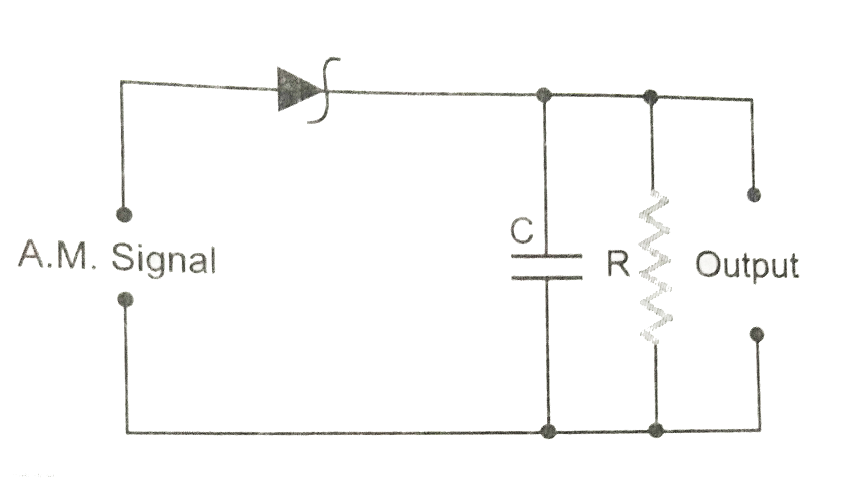
- Fig. 10 (CF).1 is the circuit diagram of an AM demodulator. For good d...
Text Solution
|
- Calculate the length of half wave dipole antenna at 30 MHz
Text Solution
|
- If both the length of an antenna and the wavelength of the signal to b...
Text Solution
|
- An 'antenna' is:
Text Solution
|
- If the highest modulating frequency of the wave is 5 kHz, the number o...
Text Solution
|
- Modulation is the process of superposing
Text Solution
|
- A carrier wave of peak voltage 15 V, is used to transmit a message sig...
Text Solution
|
- Which one of the following frequencies will be reflated back by the i...
Text Solution
|
- Troposphere is used in the propagation of
Text Solution
|
- A ratio has a power of 1 kW and is operating at a frequency of 10 GHz ...
Text Solution
|
- The height of a T. V. tower is 75 m. If we want to double its coverage...
Text Solution
|