


Similar Questions
Explore conceptually related problems
Recommended Questions
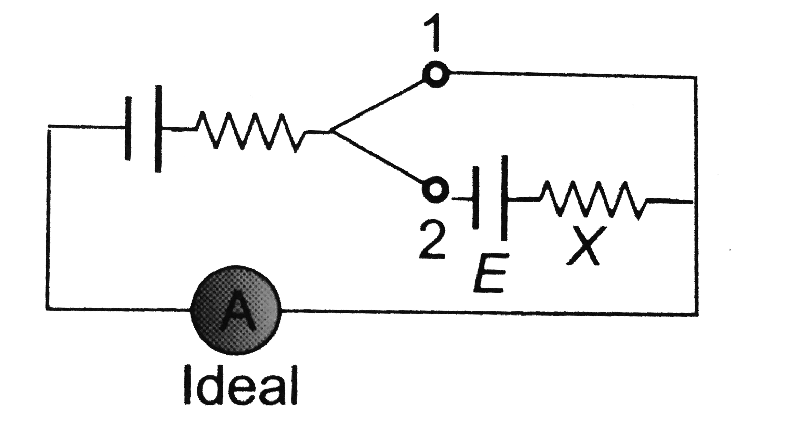
- In the circuit shown the variable resistance X is to be adjusted such ...
Text Solution
|
- In the circuit shown in figure ammeter and voltmeter are ideal. If E=4...
Text Solution
|
- Shown two ideal voltmeters and an ammeter, which are connected across ...
Text Solution
|
- In the circuit shown in Fig. 6.50, an idel ammeter and an ideal voltme...
Text Solution
|
- In the circuit shown in figure the reading of ammeter is the same with...
Text Solution
|
- In the circuit shown the variable resistance X is to be adjusted such ...
Text Solution
|
- In the circuit shown, an ideal cell of emf E is connected in series to...
Text Solution
|
- In the circuit shown in Fig. 4.25, the voltmeter reads 1.5 V, when the...
Text Solution
|
- A circuit is shown in the figure. The ratio of readings of ideal voltm...
Text Solution
|