A
B
C
D
Text Solution
Verified by Experts
The correct Answer is:


Similar Questions
Explore conceptually related problems
Recommended Questions
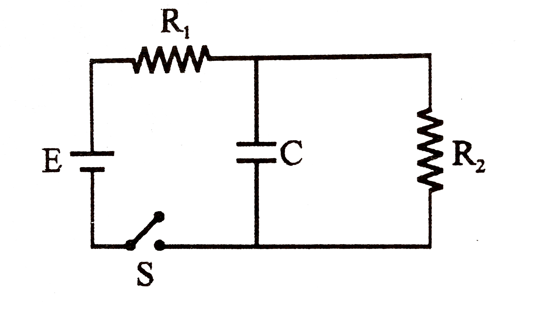
- In the circuit as shown in figure the switch is closed at t = 0. ...
Text Solution
|
- In the circuit shown in figure, the capacitor is charged with a cell o...
Text Solution
|
- Switch S is closed t=0 , in the circuit shown. The change in flux in t...
Text Solution
|
- When the switch S is closed at t=0, identify the correct statement jus...
Text Solution
|
- In the circuit shows in Fig the switch is closed at t = 0.
Text Solution
|
- In the circuit shown, the switch is closed at t=0 , the currents I1, I...
Text Solution
|
- In the circuit as shown in figure the switch is closed at t = 0 . At t...
Text Solution
|
- In the circuit as shown in figure the switch is closed at t = 0 . A lo...
Text Solution
|
- In the circuit shown in figure switch S is closed at time t=0 Cu...
Text Solution
|