A
B
C
D
Text Solution
Verified by Experts
The correct Answer is:


Similar Questions
Explore conceptually related problems
Recommended Questions
- Consider the circuit shown in the figure
Text Solution
|
- Consider the circuit shown in the figure. The current I(3) is equal to
Text Solution
|
- Consider the circuit shown in the figure
Text Solution
|
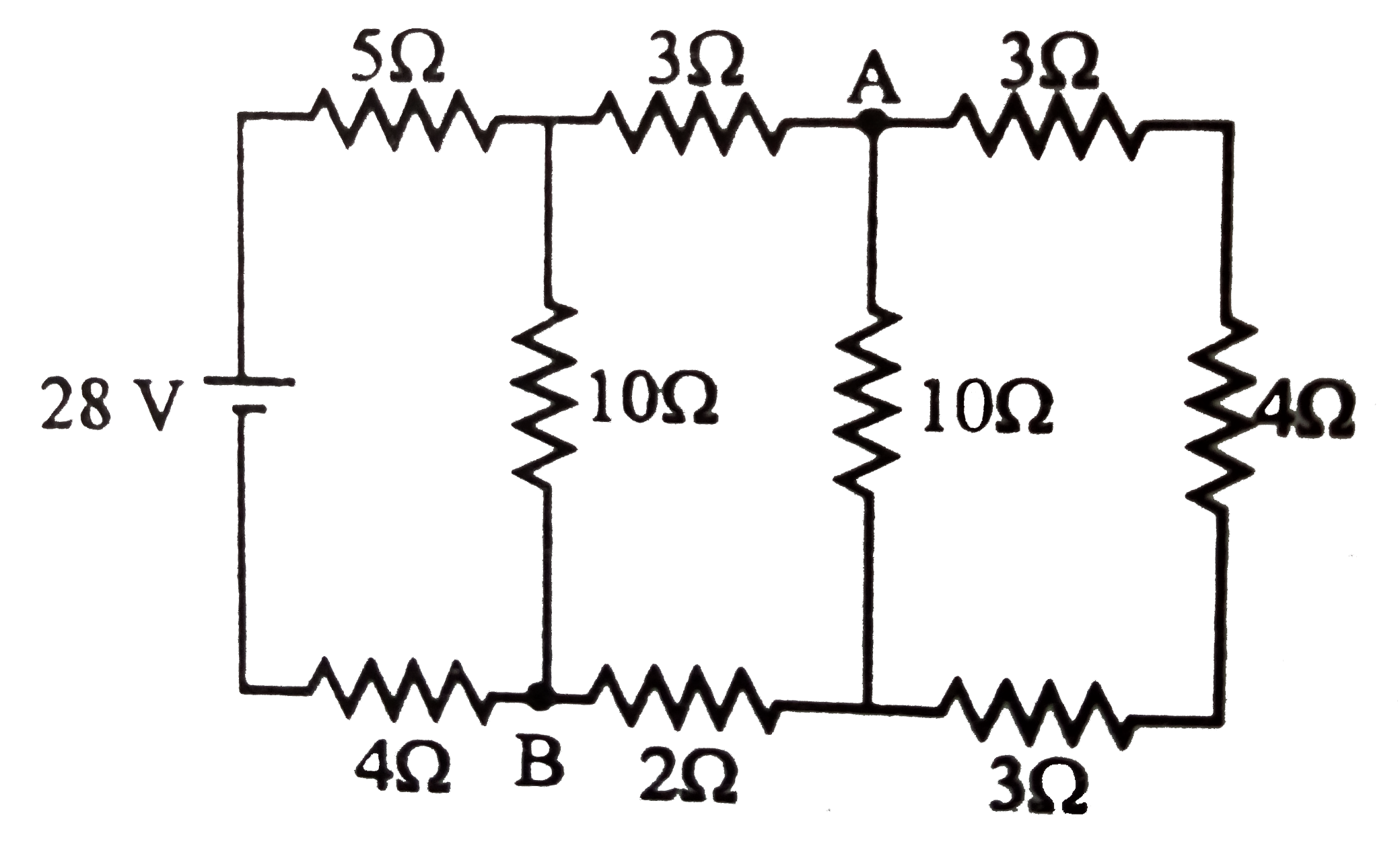
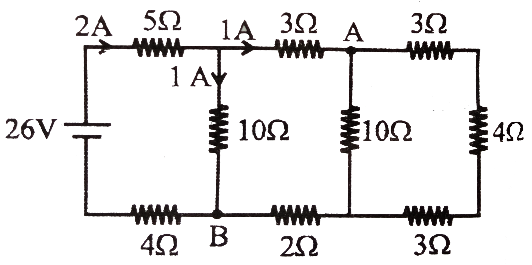
- Consider circuit as shown in figure. The current through wire AB is
Text Solution
|
- Consider the circuit as shown in figure. The equivalent resistance bet...
Text Solution
|
- Consider the circuit shown in the figure. Taking the potential to be z...
Text Solution
|
- Consider the circuit shown in figure, the current l(3) is equal to
Text Solution
|
- Consider the circuit shown in the figure. What is the value of the cur...
Text Solution
|
- Consider the circuit shown in the figure. Which of the following state...
Text Solution
|