A
B
C
D
Text Solution
Verified by Experts
The correct Answer is:


Similar Questions
Explore conceptually related problems
Recommended Questions
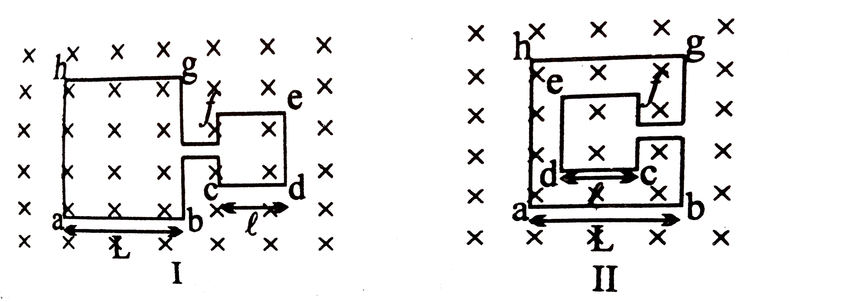
- The adjoining figure shows two different arrangements in which two squ...
Text Solution
|
- The adjoining figure shows two different arrangements in which two squ...
Text Solution
|
- The adjoining figure shows two different arrangements in which two squ...
Text Solution
|
- The adjoining figure shows two different arrangements in which two squ...
Text Solution
|
- The adjoining figure shows two different arrangements in which two squ...
Text Solution
|
- Two parallel, long wires carry current i(1) and i(2) withi(1)gti(2). W...
Text Solution
|
- Figure shows four wires placed in the same uniform magnetic field B an...
Text Solution
|
- Two long parallel straight conductors carry current i(1) and i(2)(i(1)...
Text Solution
|
- Two parallel long wire carry currents i(1) and i(2) with i(1) gt i(2) ...
Text Solution
|