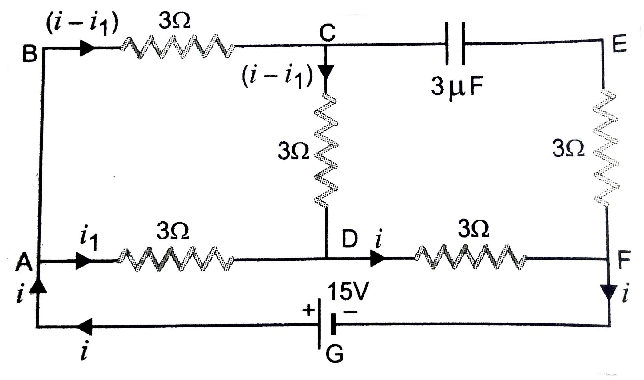
In the circuit shown in figure Find the potential differnece across capacitor.
Text Solution
Verified by Experts
When capacitor is fully charged, it fraws no currnet, and hence provides infinite resistance, then no current flows in arm EF. The potential difference across C and F. The resistance of arm AD and they together are in series with resistance of arm DF. The effective resistance between A and F of circuit is, `R = (3xx6/3+6) + 3 = 2 +3 =5 Omega` Main in the circuit, `i = 15/5=3 A` Current through arm BCD ` = 1 xx 3/6+3 = 3xx3/9 = 1 A` Potential difference across C and D `= 1 xx 3 = 3V` Current through arm DF, i =3A Potential differences across D and F `= 3 xx 3 = 9 V` So, potential difference across C and F `= 3+ 9=12 V` Thus, potential difference across the capacitor is 12 V
Topper's Solved these Questions
CURRENT ELECTRICITY
PRADEEP|Exercise Conceptual Problems|3 Videos
CURRENT ELECTRICITY
PRADEEP|Exercise Very short Q/A|7 Videos
COMMUNICATION SYSTEMS
PRADEEP|Exercise MODEL TEST PAPER-2|9 Videos
DUAL NATURE OF RADIATION AND MATTER
PRADEEP|Exercise Exercise|191 Videos
Similar Questions
Explore conceptually related problems
In a ircuit shown in figure, the potential difference across the capacitor of 2muF is
In the circuit shown in the figure, the potential difference across the 4.5 muF capacitor is
Find the current flowing through each cell in the circuit shown in figure. Also calculate the potential difference across the terminals of each cell.
In the circuit shown in the Figure, find the ratio of potential difference across capacitor 1 and 2. The capacitance values are as indicated in the Figure.
A current of 7 A flows through the circuit as shown in the figure the potential difference across points B and D is
In the network shown in given figure, find the potential difference across BD
In the circuit shown in figure potential differences across 6Omega resistance is 4 volt. Find V and i values across each resistance. Also find emf E of the applied battery.
PRADEEP-CURRENT ELECTRICITY-Problems for Practice (B)