Home
Class 12
PHYSICS
A schematic rheostat is shown in figure....

A schematic rheostat is shown in figure. Connect a battery to it so that it acts as a potential divider. Also show the output terminals.

Text Solution

Verified by Experts

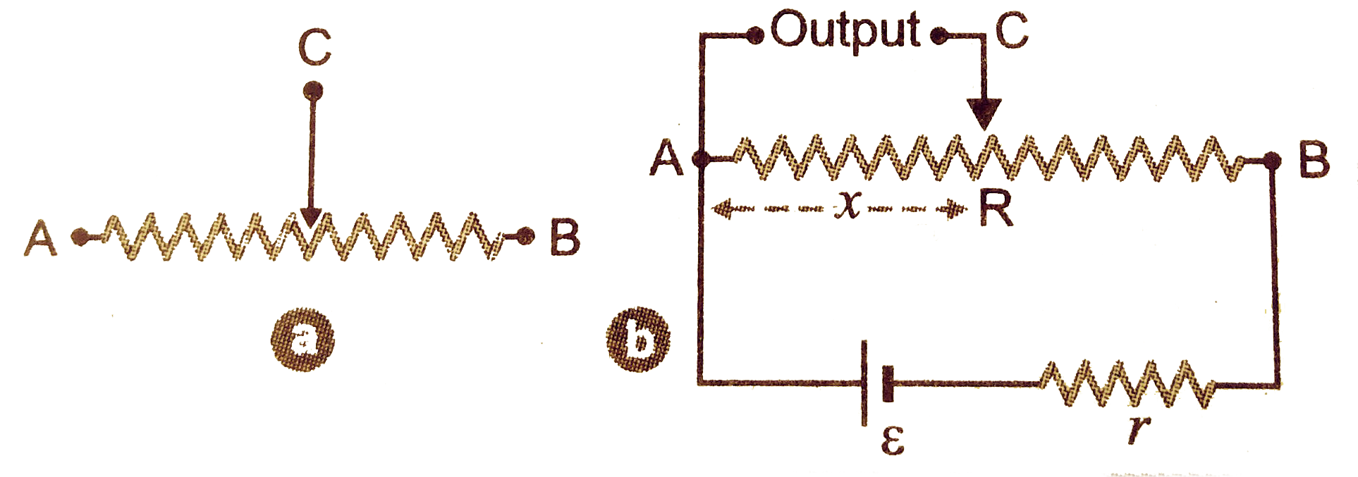
The circuit for rheostat used as potential divider is shown in figure. The out put voltage is obtained asross A and C. In this case, the output voltage is `V = ((epsilon)/(R+r))R/l x`
Where `l` is the length AB of resistance R and x is the length of resistance tapped for output. `epsilon` is the emf of battery used and r is the internal resistance of the cell.
Promotional Banner

Topper's Solved these Questions

  • CURRENT ELECTRICITY

    PRADEEP|Exercise Conceptual Problems|3 Videos
  • CURRENT ELECTRICITY

    PRADEEP|Exercise Very short Q/A|7 Videos
  • COMMUNICATION SYSTEMS

    PRADEEP|Exercise MODEL TEST PAPER-2|9 Videos
  • DUAL NATURE OF RADIATION AND MATTER

    PRADEEP|Exercise Exercise|191 Videos

Similar Questions

Explore conceptually related problems

Schematic of a rheostat is shown in the figure. Connect a battery to it so that the rheostat acts as a potential divider.Specify which are the input and output terminals

Connect a battery to the terminals and completer the circuit diagram fo that it works as a potential divider meter. Indicate the output terminals also.

Five capacitors are connected in series as shown in figure with a battery of emf 20V and the point B is earthed. The potential of point A is

In which branch of the circuit shown in figure a 11 V battery be inserted so that it dissipates minimum power. What will be the current through the 2Omega resistance for this potential of the battery?

A parallel plate capacitor has two layers of dielectrons as shown in figure. This capacitor is connected across a battery, then the ratio of potential difference across the dielectric layers is

How a battery is to be connected so that the shown rheostat will behave like a potential divider? Also indicate the points about which output can be taken. .

Find the current flowing through each cell in the circuit shown in figure. Also calculate the potential difference across the terminals of each cell.

A potential divider circuit is shown in figure.The output voltage V_(0) is: