A
B
C
D
Text Solution
Verified by Experts
The correct Answer is:


Topper's Solved these Questions
Similar Questions
Explore conceptually related problems
CP SINGH-THERMAL AND ELECTRIC EFFECT oF CURRENT-Exercises
- In the following diagram
Text Solution
|
- A part of a circuit in steady state along with the currents flowing in...
Text Solution
|
- In the diagram shown find the potential difference between the points ...
Text Solution
|
- Determine the current through the battery in the circuit shown in figu...
Text Solution
|
- The ratio of energy stored in capacitors C(1) and C(2)
Text Solution
|
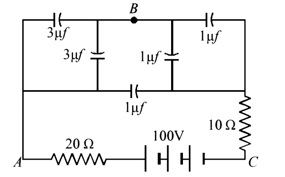
- (a) Find potential difference between A and B and C. (b) Find po...
Text Solution
|
- In the circuit shown, the cell is ideal , with emf= 15 V. Ecah resista...
Text Solution
|
- In the circuit shown, the cell is ideal with emf = 2V . The resistance...
Text Solution
|
- A capacitor charges from a cell through a resistance. The time constan...
Text Solution
|
- A capacitor is charged and then made to discharged through a resistan...
Text Solution
|
- In the circuit shown in fig. when the switch is closed, the capacitor ...
Text Solution
|
- In the previous question, if the switch is opened after the capacitor ...
Text Solution
|
- A capacitor of capacitance C has charge Q. it is connected to an ident...
Text Solution
|
- The charge on a capacitor decrease eta time in time t, when it dischar...
Text Solution
|
- Two identical capcitors A and B are charged to the same potential and ...
Text Solution
|
- a capacitor of capacitance C is connected to two voltmeter A and B. A ...
Text Solution
|
- The capacitor C is initially without charge. X is now joined to Y for ...
Text Solution
|
- The energy supplied by the cell during charging is equal to
Text Solution
|
- three identical capacitor, A, B and C are charged to the same potentia...
Text Solution
|
- Capacitor C1 of capacitance 1 micro-farad and capacitor C2 of capacita...
Text Solution
|