 .
.A
B
C
D
Text Solution
Verified by Experts
The correct Answer is:
 .
.


Topper's Solved these Questions
Similar Questions
Explore conceptually related problems
CP SINGH-ALTERNATING CURRENT-EXERCISES
- A coil of inductive reactance 31 Omega has a resistance of 8 ohm. It i...
Text Solution
|
- An L-C-R series circuit with 100Omega resistance is connected to an AC...
Text Solution
|
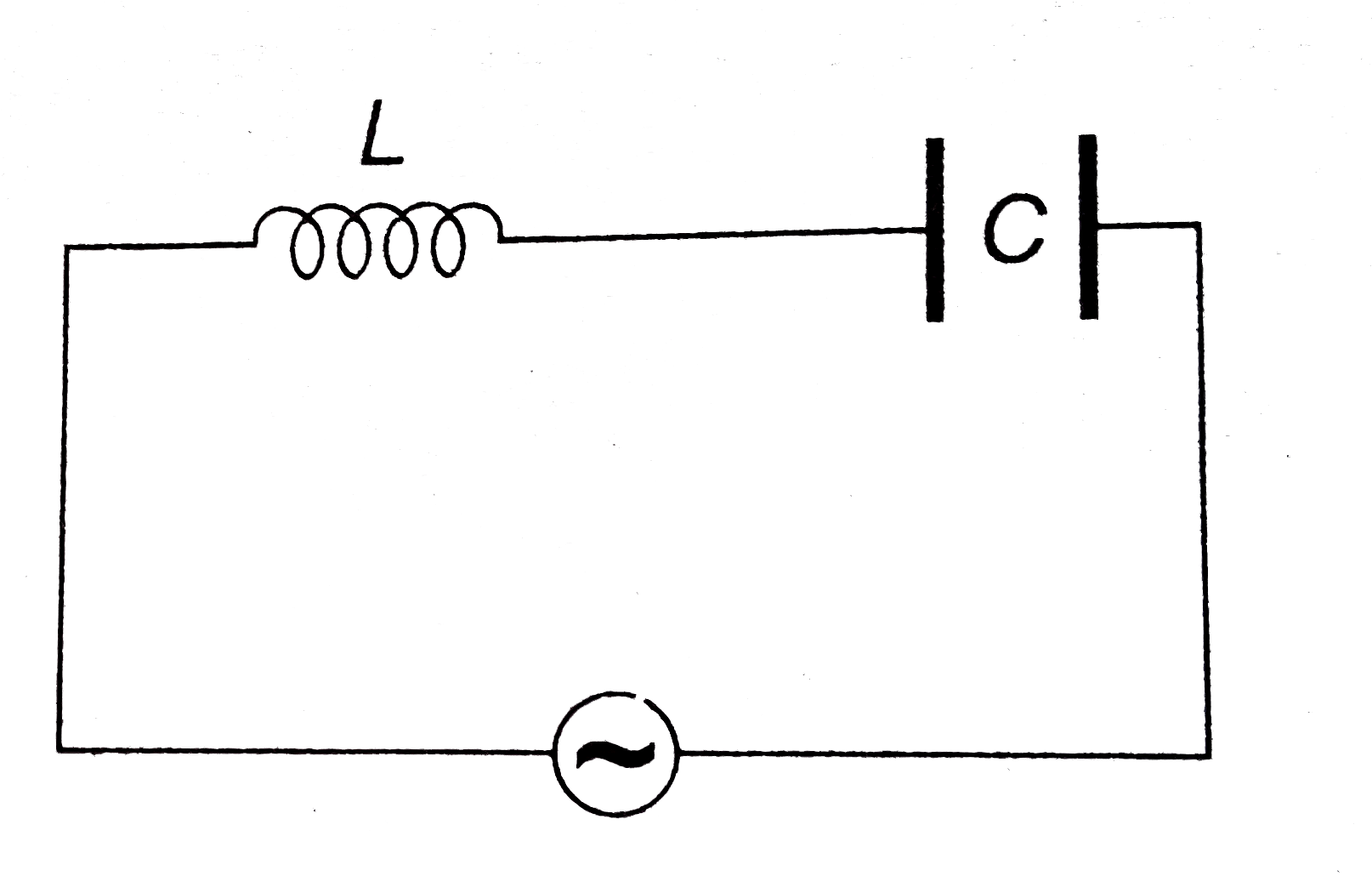
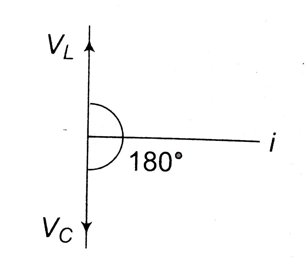
- In the circuit shown in figure the voltage in L and in C are .
Text Solution
|
- A capacitor of 10muF and an inductor of 1 H are joined in series An ac...
Text Solution
|
- The reactance of a circuit is zero It is possible that the circuit con...
Text Solution
|
- Which of the following plots may represent the reactance of a series L...
Text Solution
|
- In an a.c. Circuit the voltage applied is E=E(0) sin (omega)t. The res...
Text Solution
|
- In an AC circuit, V and I are given by V=100sin(100t)volts, I=100sin(1...
Text Solution
|
- The power in ac circuit is given by P=E(rms)I(rms)cosphi. The vale of ...
Text Solution
|
- The potential differences V and the current i flowing through an instr...
Text Solution
|
- In the given LR circuit the source has angular frequency omega The pow...
Text Solution
|
- An ac source is connected across a resistance of 10 Omega The power di...
Text Solution
|
- In an AC circuit, the power factor
Text Solution
|
- The average power dissipated in a pure inductor L carrying an alternat...
Text Solution
|
- An AC source rated 100 V (rms) supplies a current of 10 A(rms) to a ci...
Text Solution
|
- In an LCR circuit the energy is dissipated in
Text Solution
|
- Power delivered by an ac source of angular frequency Omega(0) to an LC...
Text Solution
|
- Two coils A and B are connected in series across a 240V ,50 Hz supply ...
Text Solution
|
- In previous question the resistance of coil B is
Text Solution
|
- In previous question the resistance of coil A is .
Text Solution
|