Text Solution
Verified by Experts
The correct Answer is:


Topper's Solved these Questions
Similar Questions
Explore conceptually related problems
CP SINGH-SEMICONDUCTORS-Exercises
- An oscillator is nothing but an amplifier with
Text Solution
|
- The voltage gain of an amplifier with 9% negative feedback is 10. The ...
Text Solution
|
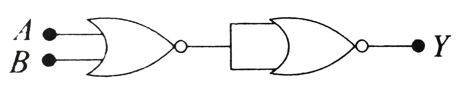
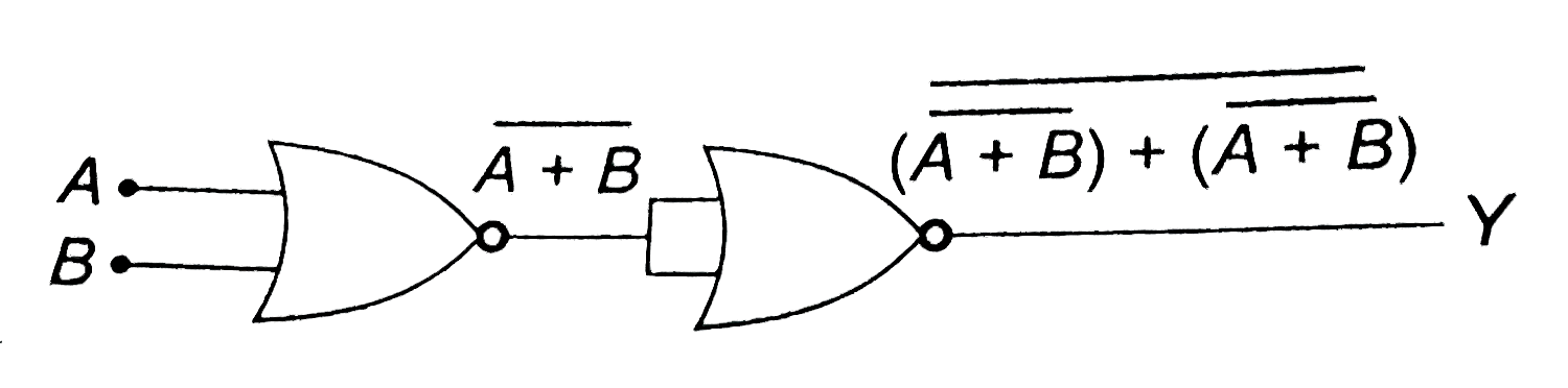
- What will be the input of A and B for the Boolean expression bar((A+B)...
Text Solution
|
- Which of these represents NAND gate?
Text Solution
|
- The circuit is equivalent to
Text Solution
|
- Which of the following gates will have an output of 1?
Text Solution
|
- The symbolic representation of four logic gates are given in Fig.The l...
Text Solution
|
- Which logic gate is represented by the following combination of logic ...
Text Solution
|
- In the following combination of logic gates, the outputs of A,B and C ...
Text Solution
|
- To get output 1for the following circuit, the correct choice for the i...
Text Solution
|
- In the following circuit, the output Y for all possible inputs A and B...
Text Solution
|
- The combination of 'NAND' gates shown here under (figure) are equivale...
Text Solution
|
- An AND gate can be prepared by repetitive use of
Text Solution
|
- The given figure shows the wave forms for two inputs A and B and that ...
Text Solution
|
- The following figure shows a logic gate circuit with two inputs A and ...
Text Solution
|
- The logic circuit shown belows has the input waveforms 'A' and 'B' as ...
Text Solution
|
- The figure shows a logic circuit with two inputs A and B and the outpu...
Text Solution
|
- The barrier potential of a p-n-junction depends on (i) Type of sem...
Text Solution
|
- The given graph represents V-I characteristic for a semiconductor devi...
Text Solution
|
- A truth table is given below. Which of the following has this types fo...
Text Solution
|