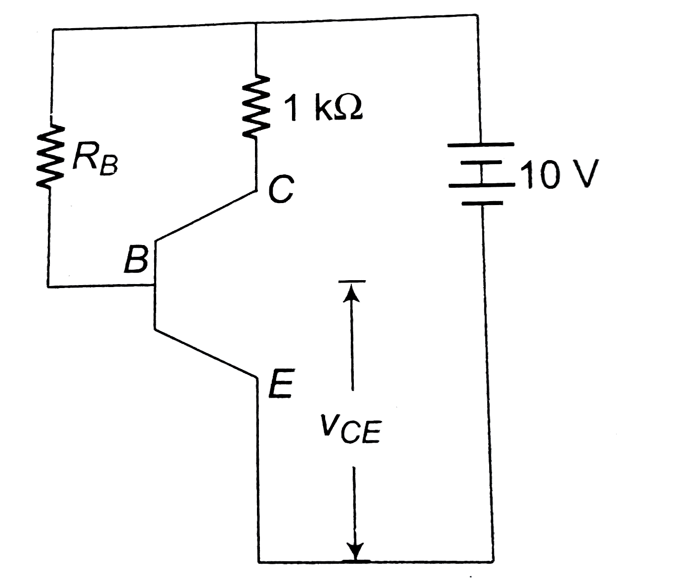
A
B
C
D
Text Solution
Verified by Experts
The correct Answer is:


Topper's Solved these Questions
SEMI CONDUCTOR DEVICES
NARAYNA|Exercise NCERT (Comprehension)|13 VideosSEMI CONDUCTOR DEVICES
NARAYNA|Exercise Level-I (H.W)|26 VideosSEMI CONDUCTOR DEVICES
NARAYNA|Exercise Level-II (C.W)|33 VideosRAY OPTICS AND OPTICAL INSTRAUMENTS
NARAYNA|Exercise EXERCISE- 4 One or more than one correct answer type|13 VideosSEMICONDUCTOR ELECTRONICS
NARAYNA|Exercise ADDITIONAL EXERCISE (ASSERTION AND REASON TYPE QUESTIONS :)|19 Videos
Similar Questions
Explore conceptually related problems
NARAYNA-SEMI CONDUCTOR DEVICES-Level-III (C.W)
- If the ratio of the concentration of electron to that of holes in a se...
Text Solution
|
- If the resistivity of copper is 1.7 xx 10^(-6) Omega cm, then the mobi...
Text Solution
|
- A pure silicon crystal of length l(0.1m) and area A(10^(-4) m^(2)) has...
Text Solution
|
- Find the current produced at room temperature in a pure germanium plat...
Text Solution
|
- An n-type semiconductor has impurity level 20 meV below the conduction...
Text Solution
|
- Assume that the number of hole-electron pair in an intrinsic semicondu...
Text Solution
|
- In the circuit shown in figure (1), the V(0),I(1),I(D(1)), and I(D(3))...
Text Solution
|
- For a junction diode, the ratio of forward current (I(f)) and reverse ...
Text Solution
|
- In the diagram D an ideal diode and an alternating voltage of peak val...
Text Solution
|
- For a CE-transistor amplifier, the audio signal voltage across the col...
Text Solution
|
- In the cuircuit shown here the transistor used has a current gain beta...
Text Solution
|
- An n - p- n transistor is connected in common - emitter configurarati...
Text Solution
|
- For a CE transistor amplifier, the audio signal voltage across the col...
Text Solution
|
- Figure shows the transfer characteristics of a base biased CE transist...
Text Solution
|
- The following configuration of gate is equivalent to
Text Solution
|
- The combination of the gates shown below produces .
Text Solution
|
- Which of the following truth tables is true ? .
Text Solution
|
- Truth table for system of four NAND gates as shown in figure is : .
Text Solution
|
- The logic circuit shown below has the input waveforms 'A' and 'B' as ...
Text Solution
|
- Logic gates X and Y have the truth tables shown below {:(P,Q,R,P,...
Text Solution
|