


Similar Questions
Explore conceptually related problems
Recommended Questions
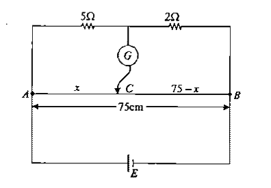
- In the meter bridge circuit shown in figure-3.281 find the length AC ...
Text Solution
|
- In the shown arrangement of the experiment of the meter bridge if AC c...
Text Solution
|
- Shown in the figure below is a meter- bridge set up will null deflecti...
Text Solution
|
- In the shows arrangement of a meter bridge, if AC corresponding to nul...
Text Solution
|
- Statement I: In the meter bridge experiment shown in figure, the balan...
Text Solution
|
- In the meter bridge circuit shown in figure-3.281 find the length AC ...
Text Solution
|
- If there is no deflection in the galvanometer connected in a circuit s...
Text Solution
|
- In the meter bridge circuit shown in figure . Find the length A...
Text Solution
|
- In the circuit of meter bridge shown in the figure.If null deflection ...
Text Solution
|