A
B
C
D
Text Solution
Verified by Experts
The correct Answer is:


Topper's Solved these Questions
ELECTRO MAGNETIC INDUCTION
NARAYNA|Exercise NCERT Based Questions|10 VideosELECTRO MAGNETIC INDUCTION
NARAYNA|Exercise Single Answer Questions Level -V|11 VideosELECTRO MAGNETIC INDUCTION
NARAYNA|Exercise Level-II (C.W)|28 VideosELECTRIC CHARGES AND FIELDS
NARAYNA|Exercise EXERCISE -4|43 VideosELECTRO MAGNETIC WAVES
NARAYNA|Exercise LEVEL-II(H.W)|14 Videos
Similar Questions
Explore conceptually related problems
NARAYNA-ELECTRO MAGNETIC INDUCTION-Level - III
- In the circuit shown below, the key K is closed at t =0. The current t...
Text Solution
|
- An equilateral triangular loop ADC having some resistance is pulled wi...
Text Solution
|
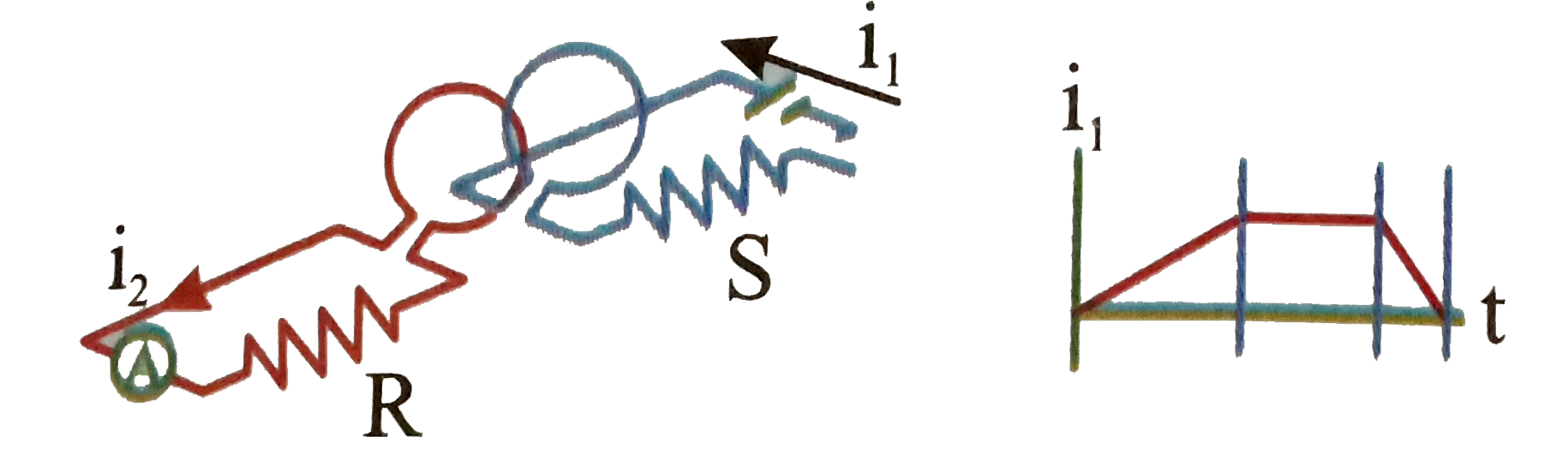
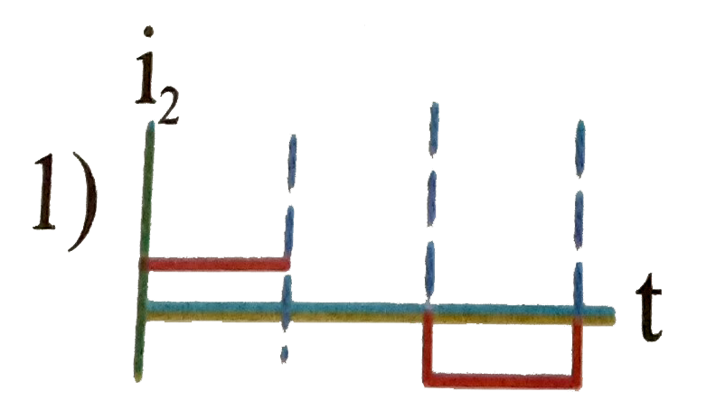
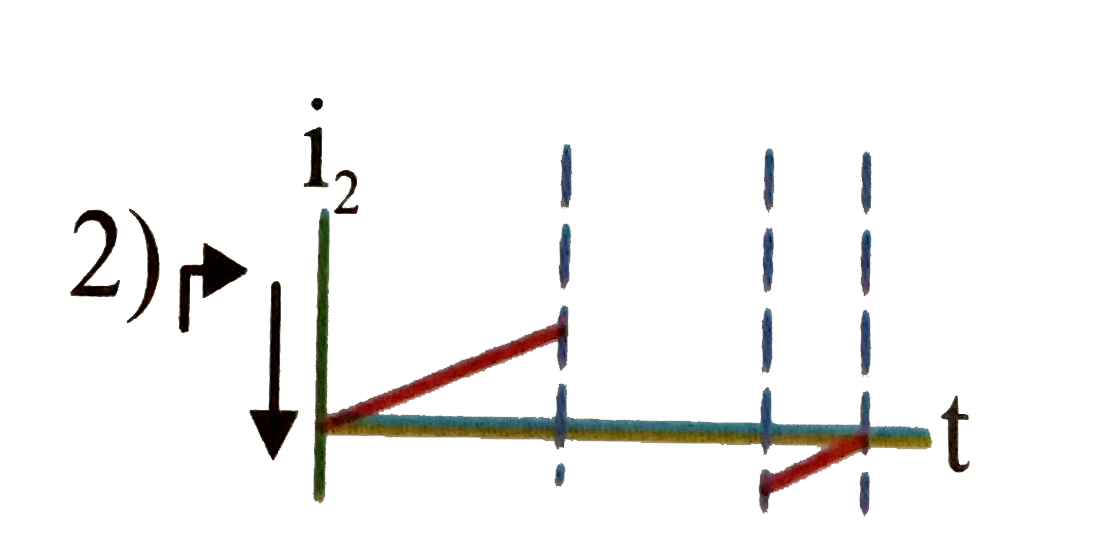
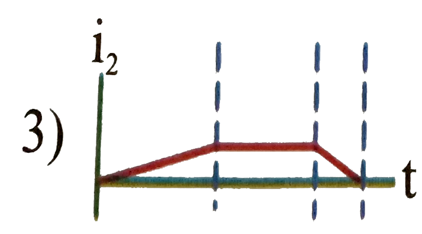
- The current through the coil in figure (i) varies as shown in figure (...
Text Solution
|
- Switch S of the circuit shows in Fig. is closed at t = 0. If e denotes...
Text Solution
|
- Switch S of the circuit shows in Fig is closed at t = 0. If e denotes ...
Text Solution
|
- A flexible conducting wire in the form of a circle is kept in a unifor...
Text Solution
|
- A wire loop is placed in a region of time varying magnetic field which...
Text Solution
|
- The current is an induction coil varies with time t, according to the ...
Text Solution
|
- A flexible wire bent in the form of a circle is place in a uniform mag...
Text Solution
|
- The inductance between A and D is
Text Solution
|
- A conduting square loop of side L and resistnce R moves in its plane w...
Text Solution
|
- Two coil are placed close to each other. The mutual inductance of the ...
Text Solution
|
- When the current changes from +2A to -2A in 0.05s, and emf of 8B is in...
Text Solution
|
- In an oscillating LC circuit the maximum charge on the capacitor is Q....
Text Solution
|
- A coil having n turns and resistance R Omega is connected with a galva...
Text Solution
|
- In a uniform magneitc field of induced B a wire in the form of a semic...
Text Solution
|
- A metal conductor of length 1m rotates vertically about one of its end...
Text Solution
|
- in a LCR circuit capacitance is chagned from C to 2C. For the resomat ...
Text Solution
|
- One conducting U tube can slide inside another as shown in figure, mai...
Text Solution
|
- The self inductance of the motor of an electric fan is 10H. In order t...
Text Solution
|