Home
Class 12
PHYSICS
If the readings V(1) and V(3) are 10. vo...

If the readings `V_(1)` and `V_(3)` are 10. volt each, then reading of `V_(2)` is:

A

0 volt

B

100 volt

C

200 volt

D

cannot be determined by given information

Text Solution

Verified by Experts

The correct Answer is:
C

Resultant voltage = 200 volt
Since `v_(1)` and `v_(3)` out of phase, the resultant voltage is equal to `v_(2)` `:. V_(2) = 200` volt
Promotional Banner

Topper's Solved these Questions

  • ALTERNATING CURRENT

    NARAYNA|Exercise LEVEL - I (H.W)|23 Videos
  • ALTERNATING CURRENT

    NARAYNA|Exercise LEVEL - II(H.W)|13 Videos
  • ALTERNATING CURRENT

    NARAYNA|Exercise LEVEL - V|83 Videos
  • ATOMIC PHYSICS

    NARAYNA|Exercise LEVEL-II (H.W)|14 Videos

Similar Questions

Explore conceptually related problems

In the given circuit the reading of voltmeters V_1 andV_2 are 300 volt each . The reading of the voltmeter V_3 and ammeter A are respectively

In the given circuit, Fig., the reading of voltmeter V_(1) and V_(2) 300 votls each. The reading of the voltemeter V_(3) and ammeter A are respectively

If the reading of volmeter V_(1) is 30 V, what is the reading of voltmeter V_(2) ?

In the figure shown R = 100 Omega L = (2)/(pi) H and C = (8)/(pi) mu F are connected in series with a.c source of 200 volt and frequency 'f' . V_(1) and V_(2) are two hot-wire voltmeters. If the readings of V_(1) and V_(2) are same then:

[" 37.In the shown circuit reading of voltmeter "V_(1)" and "V_(2)" are "300" volt each then choose correct "],[" option/options if reading of ammeter is "10A" : "],[qquad [v_(3)," O "],[" 1) "V_(2)=300V," 2) "V_(2)=500V]]

If reading of voltmeter V_(1) is 40 V, what is the reading of voltmeter V_(2) ?

In the following diagram, if the potential difference across AB is 10 V what is the reading shown by V_(2) ? How are the reading of V_(1) and V_(4) , which reading is higher ? Explains your answer (All volt metres are identified).

In an LCR series circuit, the reading of ideal voltmeters V_(1) and V_(2) are 20sqrt(2) volt and 15 volts respectively as shown in the figure (the given circuit in inductive in nature). Then

NARAYNA-ALTERNATING CURRENT-LEVEL - VI
  1. In a step-up transformer the turn's ratio is 10. If the frequency of t...

    Text Solution

    |

  2. An alternating voltage of 200 volt, at 400 cycyles//sec in applied in ...

    Text Solution

    |

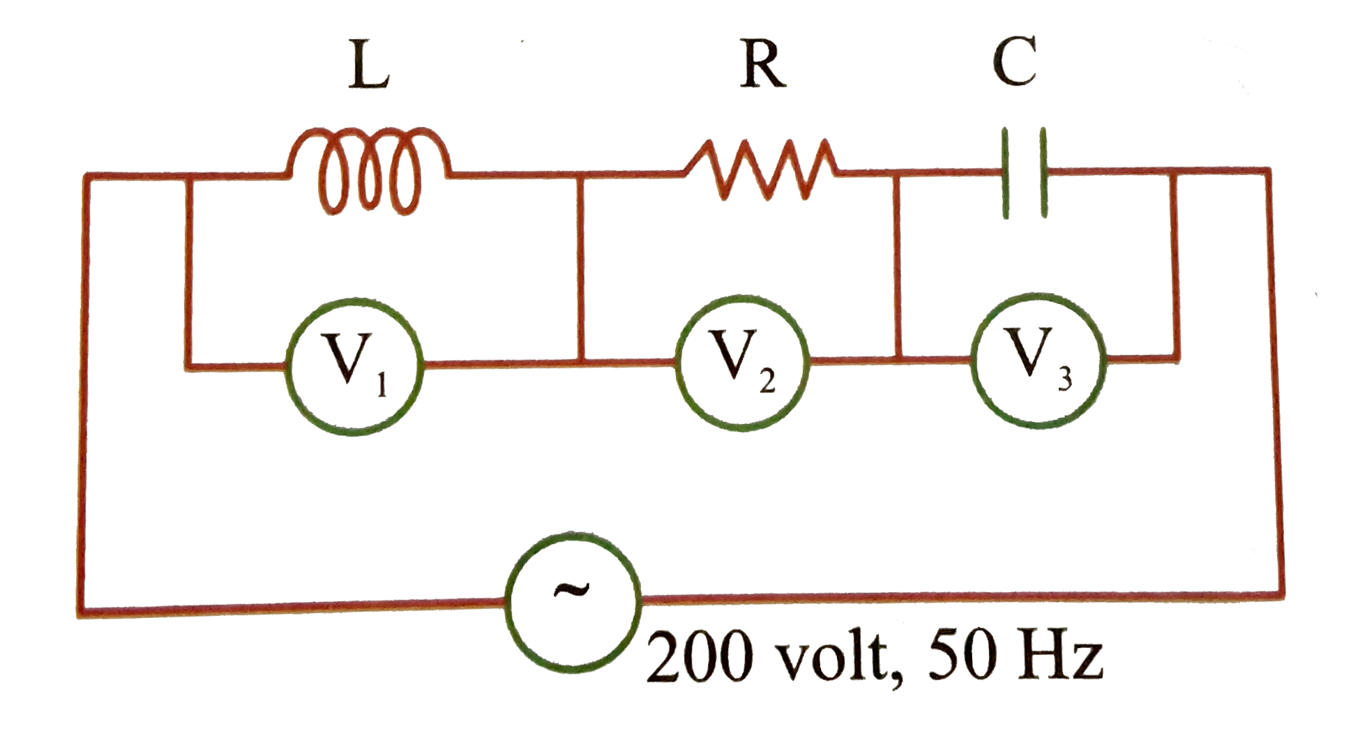
  3. If the readings V(1) and V(3) are 10. volt each, then reading of V(2) ...

    Text Solution

    |

  4. In the a.c. circuit shown in the figure. The supply voltage has a cons...

    Text Solution

    |

  5. If the power factor is 1//2 in a series RL circuit with R = 100 Omega....

    Text Solution

    |

  6. An inductor (X(L) = 2 Omega) a capacitor (X(C ) = 8 Omega) and a resis...

    Text Solution

    |

  7. A resistor of resistance 100 Omega is connected to an AC source epsilo...

    Text Solution

    |

  8. In the given AC, circuit, which of the following in incorrect:

    Text Solution

    |

  9. In the series circuit shown in the figure the voltmeter reading will b...

    Text Solution

    |

  10. In the circuit shown in fig. X(C ) = 100 Omega,(XL)=200 Omega and R=10...

    Text Solution

    |

  11. In the given circuit assuming inductor and source to be ideal, the pha...

    Text Solution

    |

  12. In the circuit current through source will be [Given (cos^(-1) (0.6)...

    Text Solution

    |

  13. In figure below if Z(1) = Z(C ) and reading of ammeter is 1A. Find val...

    Text Solution

    |

  14. As shown in figure value of inductive reactance X(L) will be (source v...

    Text Solution

    |

  15. The power factor of the circuit shown in the figure is

    Text Solution

    |

  16. In an L-R-C circuit the current is given by i = I cos omega t. The vol...

    Text Solution

    |

  17. The diagram shows a capacitor C and a resistor R connected in series t...

    Text Solution

    |

  18. Two impedances Z1 and Z2 when connected separately across a 230 V, 50 ...

    Text Solution

    |

  19. In the LCR circuit shown in figure (a) current will lead the volt...

    Text Solution

    |

  20. The A.C circuit shown in figure. Find the frequency (w(0)) of the AC v...

    Text Solution

    |