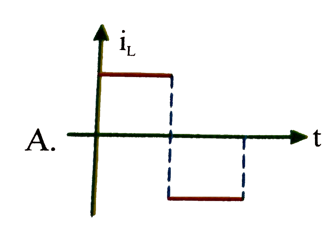
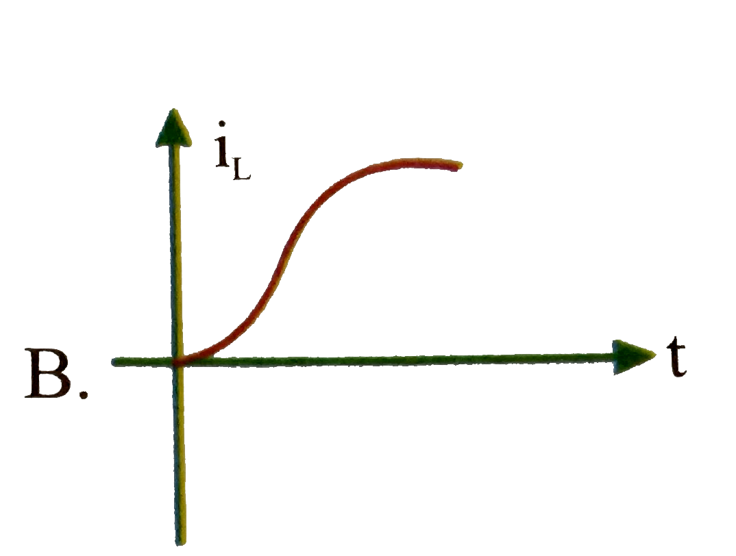
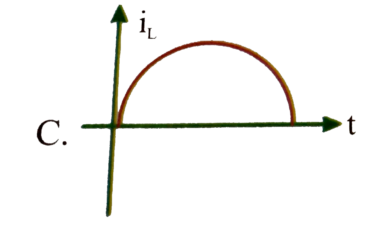
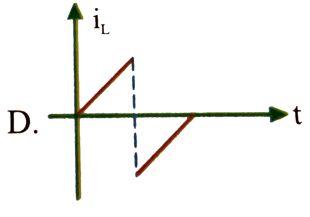
Home
Class 12
PHYSICS
The potential difference a 2 H inductor ...

The potential difference a `2 H` inductor as a function of time is shown in figure. At time `t = 0`, current is zero
Current versus time graph across the inductor will be

A

B

C

D

Text Solution

Verified by Experts

The correct Answer is:
B
Promotional Banner

Topper's Solved these Questions

  • ALTERNATING CURRENT

    NARAYNA|Exercise LEVEL - I (H.W)|23 Videos
  • ALTERNATING CURRENT

    NARAYNA|Exercise LEVEL - II(H.W)|13 Videos
  • ALTERNATING CURRENT

    NARAYNA|Exercise LEVEL - V|83 Videos
  • ATOMIC PHYSICS

    NARAYNA|Exercise LEVEL-II (H.W)|14 Videos

Similar Questions

Explore conceptually related problems

The potentiak difference across a 2H inductor as a function of time is shown in the figure. At time t=0, current is zero. Current versus time graph across the inductor will be

The potential difference across a 2 H inductor as a function of time is shown in figure. At time t=0 , current is zero Current t = 2 second is

The potential difference across a 10H inductor as a function of time is shown in the figure. At t=0 current is zero. Then

The potential difference across a 2-H inductor as a function of time is shown in Fig. At time t = 0, current is zero. Current at t = 1 s is

The potential difference across a 2-H inductor as a function of time is shown in Fig. At time t = 0, current is zero. The variation of current versus time is

The potential difference across a 2-H inductor as a function of time is shown in Fig. At time t = 0 , current is zero. Area under V_(L) - t graph gives

The potential difference across a 150 mH inductor as a function of time is shown in figure. Assume that the initial value of the current in the inductor is zero. What is the current when t=2.0 ms ? and t = 4.0 ms ?

The potential difference across a 4 H inductor vary with time is as shown. The current is Zero at t = 0, Then the current at time t =2s

Two capacitors of capacitance C and 3C are charged to potential difference V_(0) and 2V_(0) respectively, and connected to an inductor of inductance L as shown in figure. Initially the current in the inductor is zero. Now, the switch S is closed. Potential difference across capacitor of capacitance C when the current in the cirucit is maximum is

NARAYNA-ALTERNATING CURRENT-LEVEL - VI
  1. A series R-L-C circuit has R = 100 Ohm. L = 0.2 mH and C = (1)/(2) mu ...

    Text Solution

    |

  2. The potential difference across a 2 H inductor as a function of time i...

    Text Solution

    |

  3. The potential difference a 2 H inductor as a function of time is shown...

    Text Solution

    |

  4. In the given arrangement the square loop of area 10 cm^(2) rotates wit...

    Text Solution

    |

  5. In the given arrangement the square loop of area 10 cm^(2) rotates wit...

    Text Solution

    |

  6. In the given arrangement the square loop of area 10 cm^(2) rotates wit...

    Text Solution

    |

  7. A 20 V 5 watt lamp is used in ac main 220 V and frequency 50 c.p.s. ...

    Text Solution

    |

  8. A 20 V 5 watt lamp is used in ac main 220 V and frequency 50 c.p.s. ...

    Text Solution

    |

  9. A 20 V 5 watt lamp is used in ac main 220 V and frequency 50 c.p.s. ...

    Text Solution

    |

  10. In the circuit shown in the figure R = 50 Omega, E(1) = 25 sqrt(3) vol...

    Text Solution

    |

  11. In the circuit shown in the figure R = 50 Omega, E(1) = 25 sqrt(3) vol...

    Text Solution

    |

  12. In the circuit shown in the figure R = 50 Omega, E(1) = 25 sqrt(3) vol...

    Text Solution

    |

  13. A physics lab is designed to study the transfer of electrial energy fr...

    Text Solution

    |

  14. A physics lab is designed to study the transfer of electrial energy fr...

    Text Solution

    |

  15. A physics lab is designed to study the transfer of electrial energy fr...

    Text Solution

    |

  16. A physics lab is designed to study the transfer of electrial energy fr...

    Text Solution

    |

  17. In the circuit shown in figure : R = 10 Omega , L = (sqrt(3))/(10) H...

    Text Solution

    |

  18. In the circuit shown in figure : R = 10 Omega , L = (sqrt(3))/(10) H...

    Text Solution

    |

  19. In the circuit shown in figure : R = 10 Omega , L = (sqrt(3))/(10) H...

    Text Solution

    |

  20. A solenoid with inductance L=7 m H and active resistance R=44 Omega is...

    Text Solution

    |