A
B
C
D
Text Solution
Verified by Experts
The correct Answer is:


Topper's Solved these Questions
Similar Questions
Explore conceptually related problems
NARAYNA-ALTERNATING CURRENT-LEVEL - VI
- A 20 V 5 watt lamp is used in ac main 220 V and frequency 50 c.p.s. ...
Text Solution
|
- A 20 V 5 watt lamp is used in ac main 220 V and frequency 50 c.p.s. ...
Text Solution
|
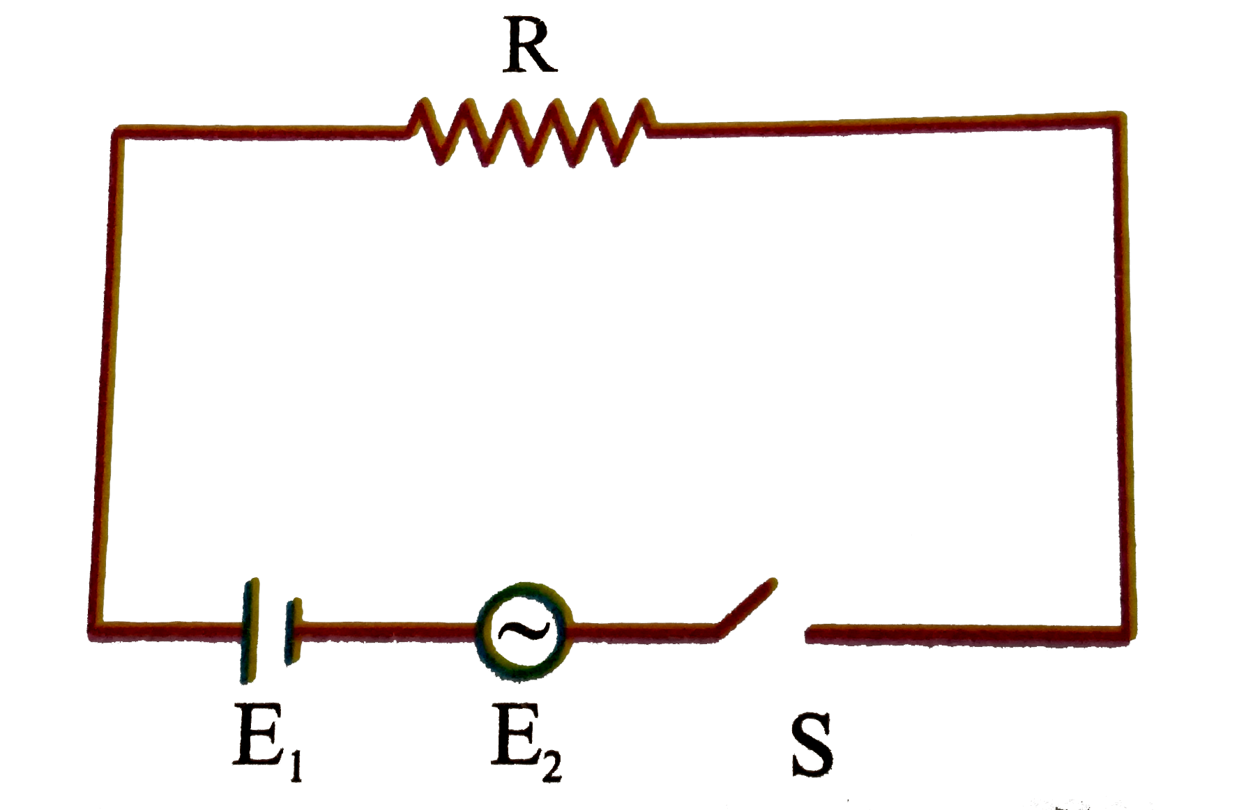
- In the circuit shown in the figure R = 50 Omega, E(1) = 25 sqrt(3) vol...
Text Solution
|
- In the circuit shown in the figure R = 50 Omega, E(1) = 25 sqrt(3) vol...
Text Solution
|
- In the circuit shown in the figure R = 50 Omega, E(1) = 25 sqrt(3) vol...
Text Solution
|
- A physics lab is designed to study the transfer of electrial energy fr...
Text Solution
|
- A physics lab is designed to study the transfer of electrial energy fr...
Text Solution
|
- A physics lab is designed to study the transfer of electrial energy fr...
Text Solution
|
- A physics lab is designed to study the transfer of electrial energy fr...
Text Solution
|
- In the circuit shown in figure : R = 10 Omega , L = (sqrt(3))/(10) H...
Text Solution
|
- In the circuit shown in figure : R = 10 Omega , L = (sqrt(3))/(10) H...
Text Solution
|
- In the circuit shown in figure : R = 10 Omega , L = (sqrt(3))/(10) H...
Text Solution
|
- A solenoid with inductance L=7 m H and active resistance R=44 Omega is...
Text Solution
|
- An LCR circuit has L = 10 mH, R = 3 Omega and C = 1 mu F connected in ...
Text Solution
|
- A series LCR circuit with R = 20 Omega, L = 1.5 H and C = 35 mu F is c...
Text Solution
|
- A sinusoidal voltage of peak value 283 V and frequency 50 Hz is applie...
Text Solution
|
- Two resistors are connected in series across 5V rms source of alternat...
Text Solution
|
- In LCR circuit current resonant frequency is 600Hz and half power poin...
Text Solution
|
- An ac ammeter is used to measure currnet in a circuit. When a given di...
Text Solution
|
- In a series LCR circuit the voltage across the resistance, capacitance...
Text Solution
|