 .
. 


Similar Questions
Explore conceptually related problems
Recommended Questions
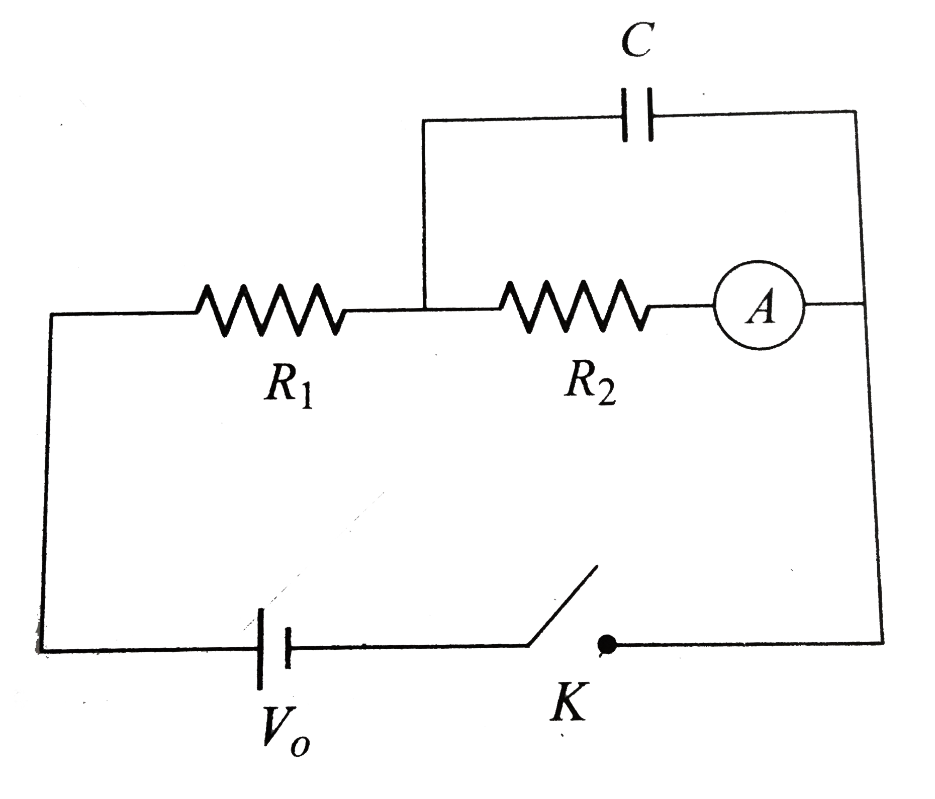
- In the connection shown in the figure, initially the switch K is open ...
Text Solution
|
- In the circuit shown in figure, the capacitors are initially uncharged...
Text Solution
|
- In the connection shown in the figure, initially the switch K is open ...
Text Solution
|
- In the connection shown in the figure, initially the switch K is open ...
Text Solution
|
- Initially the capacitor was uncharged Current in the capacitor just af...
Text Solution
|
- In the connection shown in the figure the switch K is open and the cap...
Text Solution
|
- In the circuit shown in figure-3.351 the capacitors are initially unch...
Text Solution
|
- In the given figure switch is open initially and capacitor C2 is uncha...
Text Solution
|
- In the given figure switch is open initially and capacitor C2 is uncha...
Text Solution
|