Home
Class 12
PHYSICS
(a) A metal rod of length L rotates abou...

(a) A metal rod of length `L` rotates about an end with a uniform angular velocity `omega` . A uniform magnetic field `B` exists in the direction of the axis of rotation. Calculate the emf induced between the ends of the rod. Neglect the centripetal force acting on the free electrons as they move in circular paths.
(b) A rod of length `L` rotates with a small but uniform angular velocity `omega` about its perpendicular bisector. A uniform magnetic field `B` exists parallel to the axis of rotation. Find the potential difference (i) between the centre of rod and one end and (ii) between the two ends of the rod.

Text Solution

Verified by Experts

Here the velocity of every part of rod is different. Taking an element of length `dx` at distance `x`
`de=Bvdx`
`eBomegaint_(0)^(L)xdx`
`=Bomega|(x^(2))/(2)|_(0)^(L)`
`e=(1)/(2)BomegaL^(2)` (Remember it)
`V_(0)-V_(A)=e=(1)/(2)BomegaL^(2)`
`V_(0)-V_(A)=(1)/(2)Bomega((L)/(2))^(2)=(BomegaL^(2))/(8)`
`V_(A)+e_(1)-e_(2)=V_(B)`
`V_(A)-V_(B)=0`


Promotional Banner

Topper's Solved these Questions

  • ELECTROMAGNETIC INDUCTION

    CP SINGH|Exercise EXERCISES|141 Videos
  • CURRENT ELECTRICITY

    CP SINGH|Exercise Exercise|137 Videos
  • ELECTROMAGNETIC WAVES

    CP SINGH|Exercise EXERCISES|21 Videos

Similar Questions

Explore conceptually related problems

A metal rod length l rotates about on end with a uniform angular velocity omega . A uniform magnetic field vecB exists in the direction of the axis of rotation. Calculate the emf induced between the ends of the rod. Neglect the centripetal force acting on the free electrons as they money in circular paths.

A rod of length l rotates with a small but uniform angular velocity omega about its perpendicular bisector. A uniform magnetic field B exists parallel to the axis of rotation. The potential difference between the centre of the rod and an end is

A rod of length l rotates with a uniform angular velocity omega about its perpendicular bisector. A uniform magnetic field B exists parallel to the axis of rotation. The potential difference between the two ends of the lrod is

A metal rod of length 15xx10^(-2)m rotates about an axis passing through one end with a uniform angular velocity of 60 rad s^(-1) . A uniform magnetic field of 0.1 Tesla exisits in the direction of the axis of rotationn. Calculate the EMF induced between the ends of the rod.

A conducting rod of length 2l is rotating with constant angular speed w about its perpendicular bisector. A uniform magnetic field B exists parallel to the axis of rotation. The e.m.f. induced between two ends of the rod is

A conducting rod rotates with a constant angular velocity 'omega' about the axis which passes through point 'O' and perpendicular to its length . A uniform magnetic field 'B' exists parallel to the axis of the rotation . Then potential difference between the two ends of the rod is :-

A rod of length l is rotated with angular speed omega about an axis passing through the centre of rod and perpendicular to its length. A uniform magnetic field B is applied parallel to the axis of rotation, Potential difference developed between the ends of the rod is

CP SINGH-ELECTROMAGNETIC INDUCTION-EXERCISES
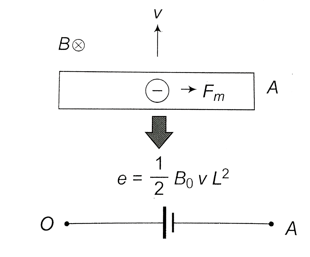
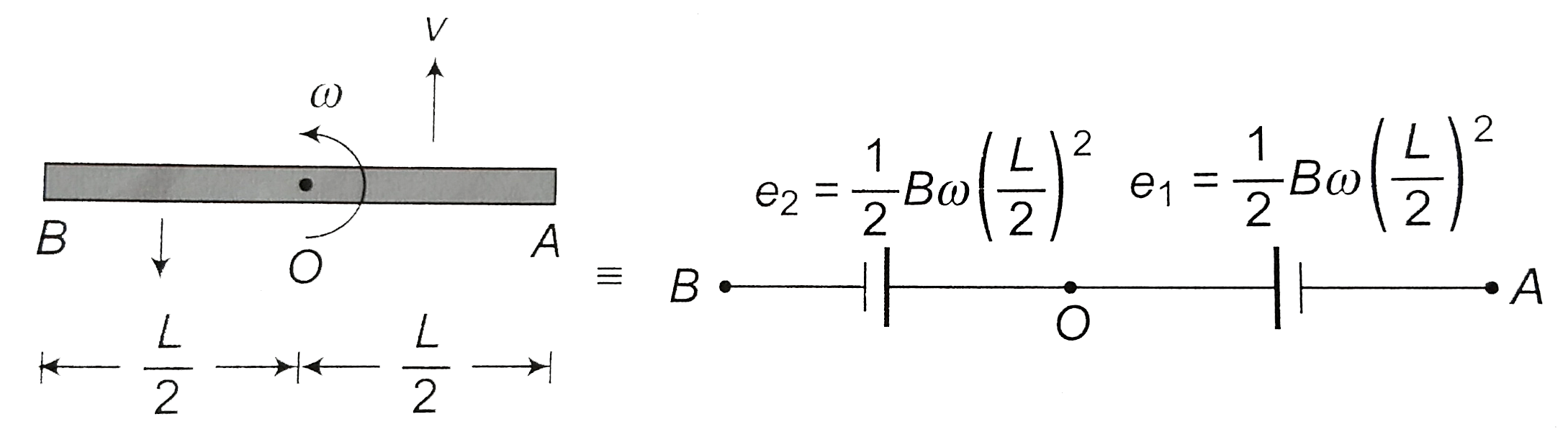
  1. (a) A metal rod of length L rotates about an end with a uniform angula...

    Text Solution

    |

  2. The direction of induced current in the loop

    Text Solution

    |

  3. A current-carrying wire is placed, below a coil in its plane, with cur...

    Text Solution

    |

  4. A wire is bent to form the double loop shown in figure. There is a uni...

    Text Solution

    |

  5. Two different wire loops are concentric and lie in the same plane. The...

    Text Solution

    |

  6. A bar magnet is moved along the axis of a copper ring placed far away ...

    Text Solution

    |

  7. Consider the situation shown in . if the switch is closed and after so...

    Text Solution

    |

  8. Solve the previous question if the closed loop is completely enclosed ...

    Text Solution

    |

  9. As shown in the figure, P and Q are two coaxial conducting loops separ...

    Text Solution

    |

  10. shows a horizontal solenoid connected to a battery and a switch. A cop...

    Text Solution

    |

  11. An aluminium ring B faces an electromagnet A. The current I through A ...

    Text Solution

    |

  12. A conduting ring R is placed on the axis of a bar magnet M . The plane...

    Text Solution

    |

  13. Two circular loops of equal radii are placed coaxially at some separat...

    Text Solution

    |

  14. Two identical coaxial circular loops carry a current i each circulatin...

    Text Solution

    |

  15. Two circular coil P and Q are arranged coaxially as shown. The sign co...

    Text Solution

    |

  16. Two circular loops P and Q are placed with their planes paraller to ea...

    Text Solution

    |

  17. A small, conducting circular loop is placed inside a long solenoid car...

    Text Solution

    |

  18. A small magnet M is allowed to fall through a fixed horizontal conduct...

    Text Solution

    |

  19. In the previous question, the directions of the current flowing in the...

    Text Solution

    |

  20. A copper ring having a cut such as not to from a complete loop is held...

    Text Solution

    |

  21. Lenz's law is consequence of the law of conservation of

    Text Solution

    |