A

B

C

D

Text Solution
Verified by Experts
The correct Answer is:


Topper's Solved these Questions
Similar Questions
Explore conceptually related problems
RESONANCE-SEMICONDUCTORS-Exercise
- In a PNP transistor working as common-base amplifier, current gain is ...
Text Solution
|
- In an NPN transistor 10^(10) electrons enter the emitter in 10^(-6)s a...
Text Solution
|
- In the following common emitter configuration an NPN transistor with c...
Text Solution
|
- An n - p- n transistor is connected in common - emitter configurarati...
Text Solution
|
- In an NPN transistor the values of base current and collector current ...
Text Solution
|
- In a common emitter circuit, if V(CE) is changed by 0.2 V, then collec...
Text Solution
|
- Which of the following statement is not true ?
Text Solution
|
- The symbolic representation of four logic gates are given in Fig.The l...
Text Solution
|
- The output of OR gate is 1
Text Solution
|
- Following diagram performs the logic function of-
Text Solution
|
- The truth table given below is for: |(A,B,X),(0,0,0),(0,1,0),(1,0,0)...
Text Solution
|
- NAND gate is-
Text Solution
|
- The truth table given below is for which gate? |(A,B,C),(0,0,1),(0,1...
Text Solution
|
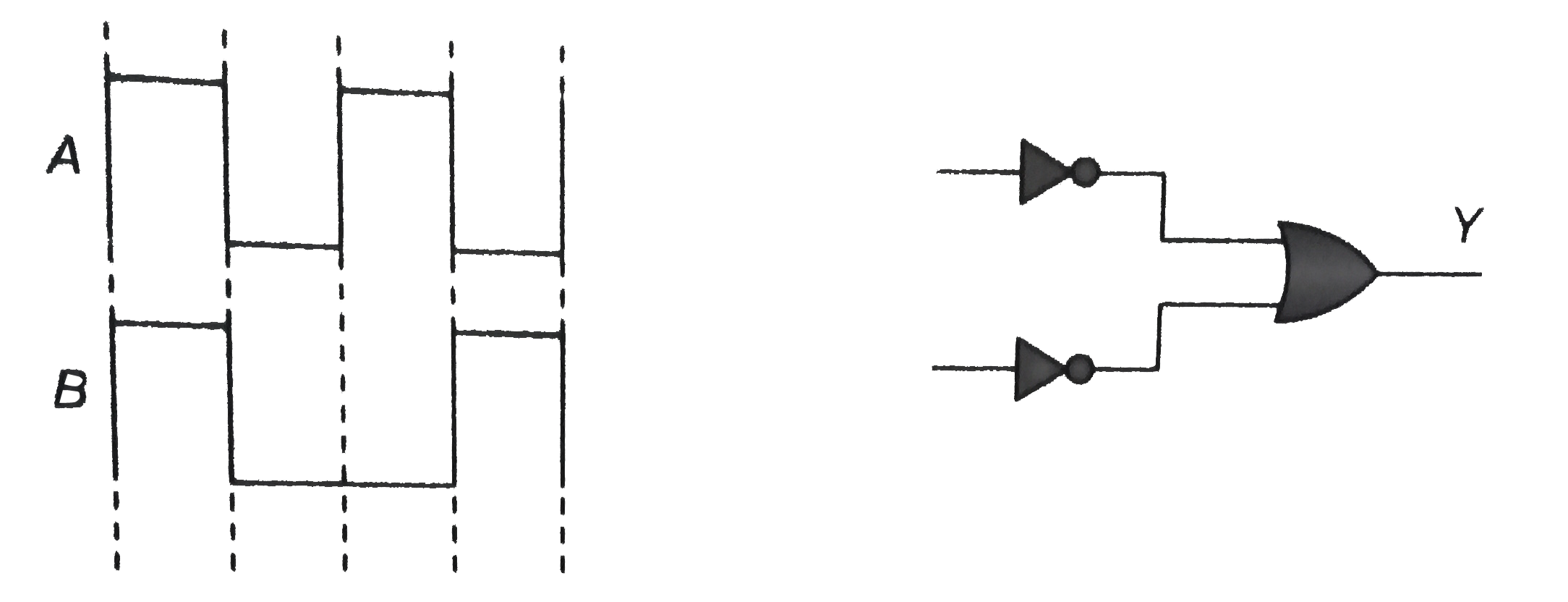
- In the given circuit as shown the two input waveform A and B are appli...
Text Solution
|
- For the logic circuit shown the boolean relation is-
Text Solution
|
- For the given combination of gates, if the logic states of inputs A,B,...
Text Solution
|
- The boolean equation of NOR gate is-
Text Solution
|
- According to de morgan's theorem-
Text Solution
|
- What will be the input of A and B for the Boolean expression bar((A+B)...
Text Solution
|
- The Boolean expression for the output Y of the logic operation shown i...
Text Solution
|