A
B
C
D
Text Solution
Verified by Experts
The correct Answer is:


Topper's Solved these Questions
Similar Questions
Explore conceptually related problems
RESONANCE-CURRENT ELECTRICITY-Exercise
- A current of 2amp is flowing in the primary circuit of a potentiometer...
Text Solution
|
- For the same potential difference, a potentiometer wire is replaced by...
Text Solution
|
- If the current in a potentiometer increases, the position of the null ...
Text Solution
|
- In a potentiometer wire, whose resistance in 0.5 ohm//m, a current of ...
Text Solution
|
- The potentiometer wire 10m long and 20 ogm resistance is connected to ...
Text Solution
|
- The length of a potentiometer wire is 10m and a potential difference o...
Text Solution
|
- The potential gradient of potentiometer is 0.2 "volt"//m. A current of...
Text Solution
|
- The emf of a standard cell is 1.5 volt and its balancing length is 7.5...
Text Solution
|
- The resistance of a galvanometer coil is R. What is the shunt resistan...
Text Solution
|
- For measurement of potential difference, potentiometer is perferred in...
Text Solution
|
- Resistivity of potentiometer wire is 10^(-7) ohm metre and its area of...
Text Solution
|
- In electrolysis the mass deposited on an electrode is directly proport...
Text Solution
|
- An ammeter and a voltmeter are joined in sereis to a cell. Their readi...
Text Solution
|
- The resistance of an ammeter is 13 Omega and its scale is graduated fo...
Text Solution
|
- Three resistance P, Q, R each of 2 Omega and an unknown resistance S f...
Text Solution
|
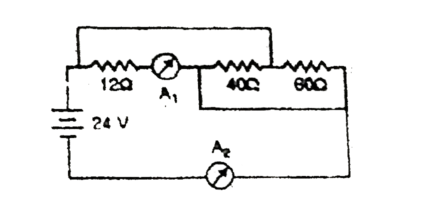
- In the circuit of figure A1 and A2 are ideal ammeters. Then the readin...
Text Solution
|
- There is a voltmeter in a circuit. In order to triple its range, the r...
Text Solution
|
- Sensitivity of potentiometer can be increased by
Text Solution
|
- STATEMENT 1: The current density vec J at any point in ohmic resistor ...
Text Solution
|
- Statement-1 : In a Meter Bridge experiment, null point for an unknown ...
Text Solution
|