Home
Class 11
PHYSICS
In the circuit shown in fig. C1 = 2C2 In...

In the circuit shown in fig. `C_1 = 2C_2` Initially, capacitor `C_1` is charged to a potential of V. The current in the circuit just after the switch S is closed is

A

0

B

`(2V)/R`

C

Infinite

D

`V/(2R)`

Text Solution

Verified by Experts

The correct Answer is:
D

at t=0
`i=V/(2R)`
Promotional Banner

Topper's Solved these Questions

  • CALORIMETRY AND THERMAL EXPANSION

    RESONANCE|Exercise Advanced Level Problems|13 Videos
  • CENTRE OF MASS

    RESONANCE|Exercise Exercise|44 Videos

Similar Questions

Explore conceptually related problems

In the circuit shown in figure C_(1) = 2 C_(2) . Capacitance C_(1) is charged to a potential of V. The current in the circuit just after the switch S is closed is

In the circuit shown in figure-3.345 the capacitor of capacitance C is charged to a potential difference V. The current in the circuit just after the closing of switch S is :

n the circuit shown in the figure, the capacitor C is charged to a potential V_(o) The heat generated and charge flow, in the circuit to when the switch S is closed, is

The circuit consists of two resistors (of resistance R_(1) = 20 Omega and R_(2) = 10 Omega ), a capacitor (of capacitance C =10 muF ) and two ideal cells. In the circuit shown the capacitor is in steady state and the switch S is open The current through the resistor R_(2) just after the switch S is closed is :

In the circuit shown in figure 3.242 capacitor is charged with 50muC charge. Find the current in 4Omega resistance just after switch S is closed.

In the circuit shown in fig. when the switch is closed, the capacitor charges with a time constant

In which of the following circuits is the current maximum just after the switch S is closed?

In the circuit shown in figure-3.351 the capacitors are initially uncharged. The current through resistor PQ just after closing the switch is :

RESONANCE-CAPACITOR-Exercise
  1. A capacitor is conneted to a cell emf E having some internal resistanc...

    Text Solution

    |

  2. For the circuit shown in the diagram find the value of Va - Vb after l...

    Text Solution

    |

  3. A 4mu F capacitor is charged to 400 volts and then its plates are join...

    Text Solution

    |

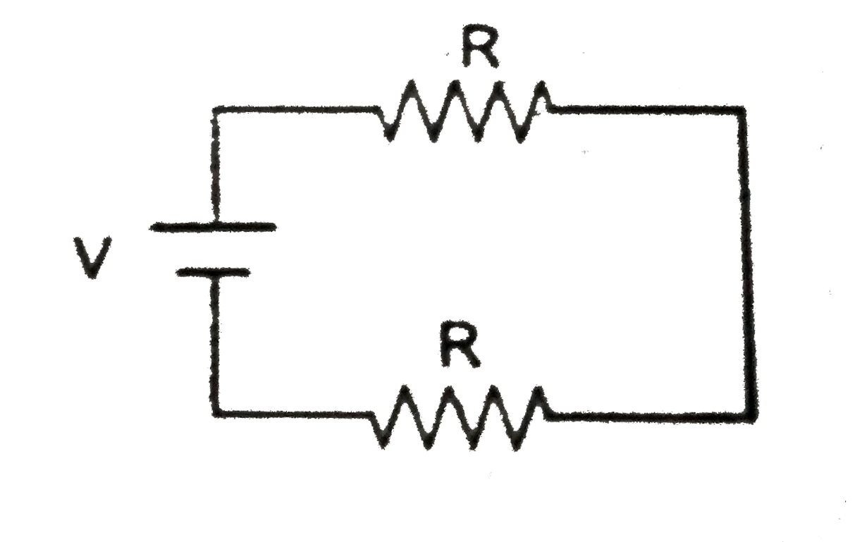
  4. The time constant of charging of the circuit shown in figure is

    Text Solution

    |

  5. Time constant of a C-R circuit is 2/(ln(2)) second. Capacitor is disch...

    Text Solution

    |

  6. In the circuit shwon in fig. switch S is closed at time t = 0. Let I1 ...

    Text Solution

    |

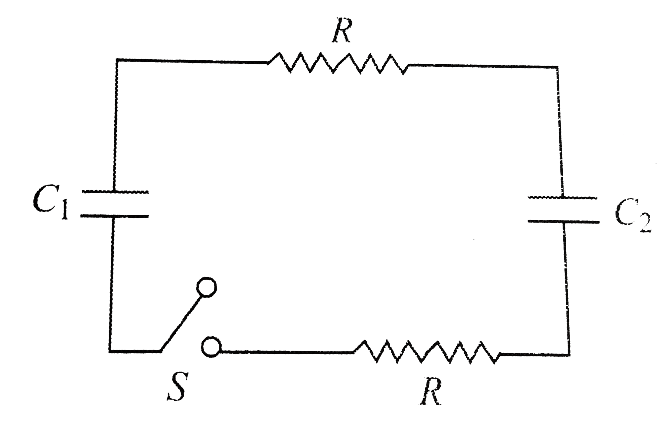
  7. In the circuit shown in fig. C1 = 2C2 Initially, capacitor C1 is charg...

    Text Solution

    |

  8. A capacitor of capacitance 500muF is charged at the rate of 100muC//s....

    Text Solution

    |

  9. A capacitor when charged by a potential difference of 200 Volts, store...

    Text Solution

    |

  10. If the two plates of the charged capacitor are connected by a wire, th...

    Text Solution

    |

  11. An air capacitor is charged upto a potential V1. It is connected in pa...

    Text Solution

    |

  12. As shown in Fig, a dielectric material of dielectric constant K is ...

    Text Solution

    |

  13. A parallel plate capacitor of plate area A and separation d is filled ...

    Text Solution

    |

  14. Two identical capacitors 1 and 2 are connected in series to a batery a...

    Text Solution

    |

  15. After charging a capacitor the battery is removed. Now by placing a di...

    Text Solution

    |

  16. Two identical capacitors A and B shown in the given circuit are joined...

    Text Solution

    |

  17. Between the plates of a parallel plate condenser, a plate of thickness...

    Text Solution

    |

  18. To reduce the capacitance of parallel plate capacitor, the space betwe...

    Text Solution

    |

  19. The capacity of a parallel plate condenser without any dielectric is C...

    Text Solution

    |

  20. A parallel plate condenser has a unifrom electric field E (V//m) in th...

    Text Solution

    |