Text Solution
Verified by Experts
_S01_099_S01.png)


Topper's Solved these Questions
Similar Questions
Explore conceptually related problems
ALLEN-WAVES AND OSCILLATIONS-Part-3(Example)
- What is an ideal diode ? Draw the output waveform across the load resi...
Text Solution
|
- A potential barrier of 0.50V exists across a p-n junction.(a) If the d...
Text Solution
|
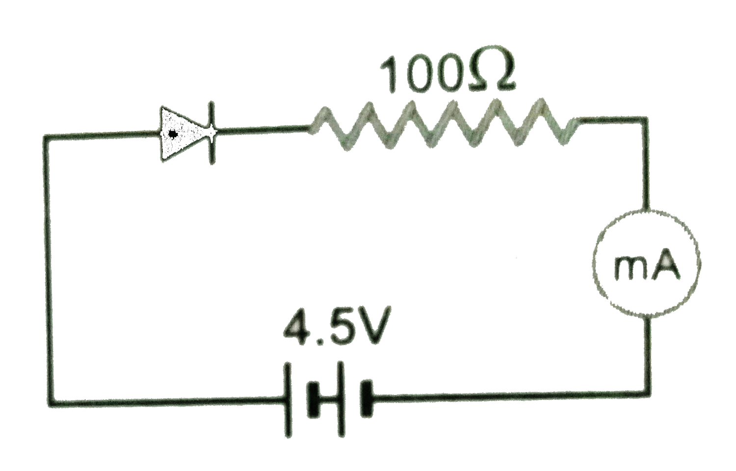
- Figure Shows a diode connected to an external resistance and an e.m.f...
Text Solution
|
- Differentiate zener and avalance breakdown.
Text Solution
|
- A sinusoidal voltage of amplitude 25 volts and frequency 50 Hz is appl...
Text Solution
|
- The halfwave rectifier supplies power to be 1 k Omega. The input suppl...
Text Solution
|
- A fullwave rectifier supplies a load of 1 k Omega. The a.c voltage app...
Text Solution
|
- A fullwave P.N diode rectifier used load resistor of 1500 Omega. No fi...
Text Solution
|
- A zener diode of voltage V(Z)(=6 volt) is used to maintain a constant ...
Text Solution
|
- A Zener diode is specified having a breakdown voltage of 9.1 V with a ...
Text Solution
|
- In a transistor, the value of beta is 50. Calculate the value of alpha
Text Solution
|
- Calculate the collector and emitter current for which I(b) = 20 mA, be...
Text Solution
|
- For a common emitter amplifier, current gain = 50. If the emitter curr...
Text Solution
|
- Transistor with beta = 75 is connected to common-base configuration. W...
Text Solution
|
- The base current is 100 muA and collector current is 3 mA (a) Calcul...
Text Solution
|
- In npn transistor circuit, the collector current us 10 mA. If 95 % of ...
Text Solution
|
- In an NPN transistor 10^(10) electrons enter the emitter in 10^(-6)s a...
Text Solution
|
- TV transmission tower at Kota has a height of 80 m. Radius of earth is...
Text Solution
|
- A ground reciver is receiving a signal at (a) 5 MHz, and (b) 100 MHz, ...
Text Solution
|
- A separate high freq. wave (i.e. carrier wave) is needed in modulation...
Text Solution
|