A
B
C
D
Text Solution
Verified by Experts


Topper's Solved these Questions
Similar Questions
Explore conceptually related problems
DISHA-ELECTROSTATICS-physics
- The false statement are, on increasing the distance between the plates...
Text Solution
|
- The capacitance of a parallel plate condenser depends on (1) Area of...
Text Solution
|
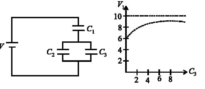
- Capacitor C(3) in the circuit is variable capacitor (its capacitance c...
Text Solution
|
- Capacitor C(3) in the circuit is variable capacitor (its capacitance c...
Text Solution
|
- Capacitor C(3) in the circuit is variable capacitor (its capacitance c...
Text Solution
|
- Assertion: The force with which one plate of a parallel plate capacito...
Text Solution
|
- Assertion: Circuit containing capacitors should be handled cautiously ...
Text Solution
|
- Assertion: If the distance between parallel plates of a capacitor is h...
Text Solution
|
- In the electric field of a point chargde q, a cetrain charge is carrie...
Text Solution
|
- Four equal charges Q are placed at the four corners of a square of eac...
Text Solution
|
- A particle A has chrage +q and a particle B has charge +4q with each o...
Text Solution
|
- In the firgure the charge Q is at the centre of the circle. Work done...
Text Solution
|
- How much kinetic energy will be gained by an alpha-particle in going f...
Text Solution
|
- Ten electrons are qually spaced and fixed around a circle of radius R....
Text Solution
|
- The displacement of a charge Q in the electric field vec(E) = e(1)hat(...
Text Solution
|
- As shown in the figure, charges +q and -q are placed at the vertices B...
Text Solution
|
- Two electric charges 12 mu C and -6 mu C are placed 20 cm apart in air...
Text Solution
|
- In the rectangle, shown below, the two corners have charges q(1) = - 5...
Text Solution
|
- Electric charges q, q, –2q are placed at the corners of an equilateral...
Text Solution
|
- A charge (-q) and another charge (Q) are kept at two points A and B re...
Text Solution
|