A
B
C
D
Text Solution
Verified by Experts


Similar Questions
Explore conceptually related problems
DISHA-ALTERNATING CURRENT-PHYSICS
- In an alternating current circuit in which an inductance and capacitan...
Text Solution
|
- A coil has resistance 30 ohm and inductive reactance 20 ohm at 50 Hz f...
Text Solution
|
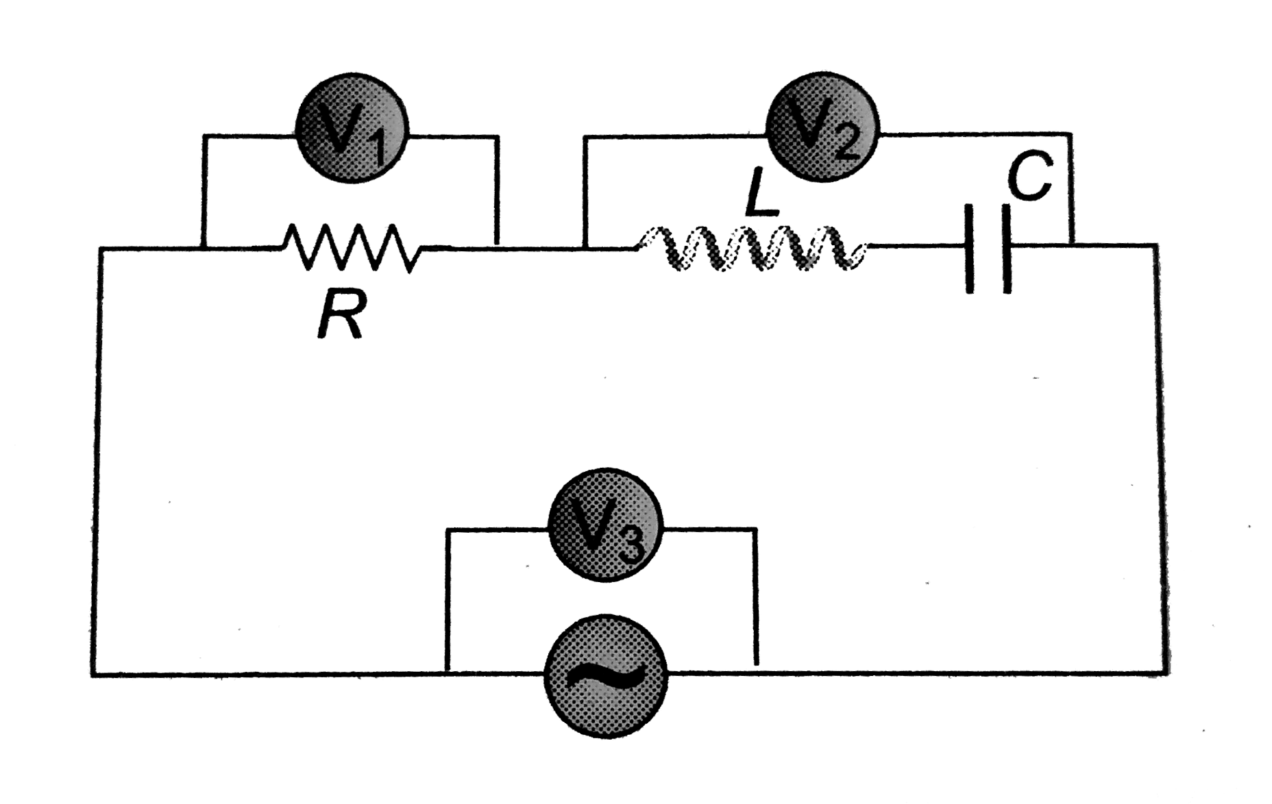
- In the figure shown, three AC voltmeters have been connected. At reson...
Text Solution
|
- A.C. power is transmitted from a power house at a high voltage as
Text Solution
|
- A transformer has an efficiency of 80%. It works at 4 kW and 100 V. If...
Text Solution
|
- A 12 ohm resistor and a 0.21 henry inductor are connected in series to...
Text Solution
|
- In LCR series circuit fed by a DC source, how does the amplitude of ch...
Text Solution
|
- The primary and secondary coils of a transmformer have 50 and 1500 tur...
Text Solution
|
- The primary winding of a transformer has 100 turns and its secondary w...
Text Solution
|
- The resistance in the following circuit is increase at a particle inst...
Text Solution
|
- The current in a LR circuit builds up to 3/4th of its steady state val...
Text Solution
|
- An LCR circuit is connected to a source of alternating current. At res...
Text Solution
|
- What is the value of inductance L for which the current is a maximum i...
Text Solution
|
- In the circuit of Fig, the bulb will become suddenly bright if
Text Solution
|
- The voltage of an ac source varies with time according to the equation...
Text Solution
|
- The current (I) in the inductance is varying with time according to th...
Text Solution
|
- Using an ac voltmeter, the potential difference in the electrical line...
Text Solution
|
- In the circuit shown in fig. when the switch is closed, the capacitor ...
Text Solution
|
- A 100 mF capacitor in series with a 40Omega resistance is connected to...
Text Solution
|
- The core of any transformaer is laminated so as to
Text Solution
|