Home
Class 11
PHYSICS
The circuit diagram (see fig.) shows a '...

The circuit diagram (see fig.) shows a 'logic combination' with the states outputs `X,Y` and `Z` given for input `P,Q,R` and `S` all at state `1` (i.e., high). When inputs `P` and `R` change to state `0` i.e., low) with inputs `Q` and `S` still at `1`, the condition of output `X,Y` and `Z` chages to

A

`1,0,0`

B

`1,1,1`

C

`0,1,0`

D

`0,0,1`

Text Solution

Verified by Experts

Promotional Banner

Topper's Solved these Questions

  • RAY OPTICS AND OPTICAL INSTRUMNTS

    DISHA|Exercise PHYSICS|44 Videos
  • SYSTEM OF PARTICLES AND ROTATIONAL MOTION

    DISHA|Exercise PHYSICS|45 Videos

Similar Questions

Explore conceptually related problems

The diagram shows a logic network. If the inputs L,M and N are all at logic 1 , what are the logic states of P,Q and R ?

In the circuit shown, inputs A and B are in states '1' and '0' respectively. What is the only possible stable state of the outputs 'X' and 'Y'?

In the given circuit P and Q from the inputs. The output Y is

For the given combination of gates, if the logic states of inputs A,B,C are as follows A=B=C=-0 and A=B=1,C=0 then the logic states of output D are

Identify the logic gates marked P and Q in the given logic circuit Fig. Write down then output at X for the inputs (i) A=0,B=0 and (ii) A=1, B=1 .

Identify the logic gate markeed P and Q in the given logic circuit Fig . Write down the output at X for the inputs (i) A=0,B=0 and (ii) A=1, B=1 .

For the given combination of gates, if the logic states of inputs A,B,C, are as follows A=B=C=0 and A=B=1, C=0 then the logic states of output D are

For the given combination of gates, if the logic states of inputs A,B,C, are as follows A=B=C=0 and A=B=1, C=0 then the logic states of output D are

DISHA-SEMICONDUCTOR-PHYSICS
  1. A PN - junction has a thickness of the order of

    Text Solution

    |

  2. A working transitor with its three legs marked P, Q and R is tested us...

    Text Solution

    |

  3. If a p-n junction diode, a square input signal of 10 V is applied as s...

    Text Solution

    |

  4. When N-type of semiconductor is heated

    Text Solution

    |

  5. The ratio of electron and hole currents in a semiconductor is 7/4 and ...

    Text Solution

    |

  6. C and Si both have same lattice structure, having 4 bonding electrons ...

    Text Solution

    |

  7. Which one of the following represents forward bias diode?

    Text Solution

    |

  8. An oscillator is nothing but an amplifier with

    Text Solution

    |

  9. The current gain in the common emitter mode of a transistor is 10. The...

    Text Solution

    |

  10. The input signal given to a CE amplifier having a voltage gain of 150 ...

    Text Solution

    |

  11. In the use of transistor as an amplifier

    Text Solution

    |

  12. A piece of copper and another of germanium are cooled from room temper...

    Text Solution

    |

  13. A d.c. battery of V volt is connected to a series combination of a res...

    Text Solution

    |

  14. The current gain for a transistor working as a common-base amplifier i...

    Text Solution

    |

  15. In the circuit below, A and B represents two inputs and C represents t...

    Text Solution

    |

  16. The i-V characteristic of a p-n junction diode is shown in figure.Find...

    Text Solution

    |

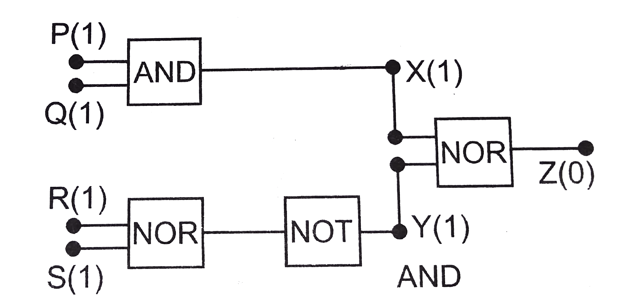
  17. The circuit diagram (see fig.) shows a 'logic combination' with the st...

    Text Solution

    |

  18. The following configuration of gate is equivalent to

    Text Solution

    |

  19. A p-n photodiode is made of a material with a band gap of 2.0 eV. The ...

    Text Solution

    |

  20. The average value of output direct current in a full wave rectifier is

    Text Solution

    |