


Similar Questions
Explore conceptually related problems
Recommended Questions
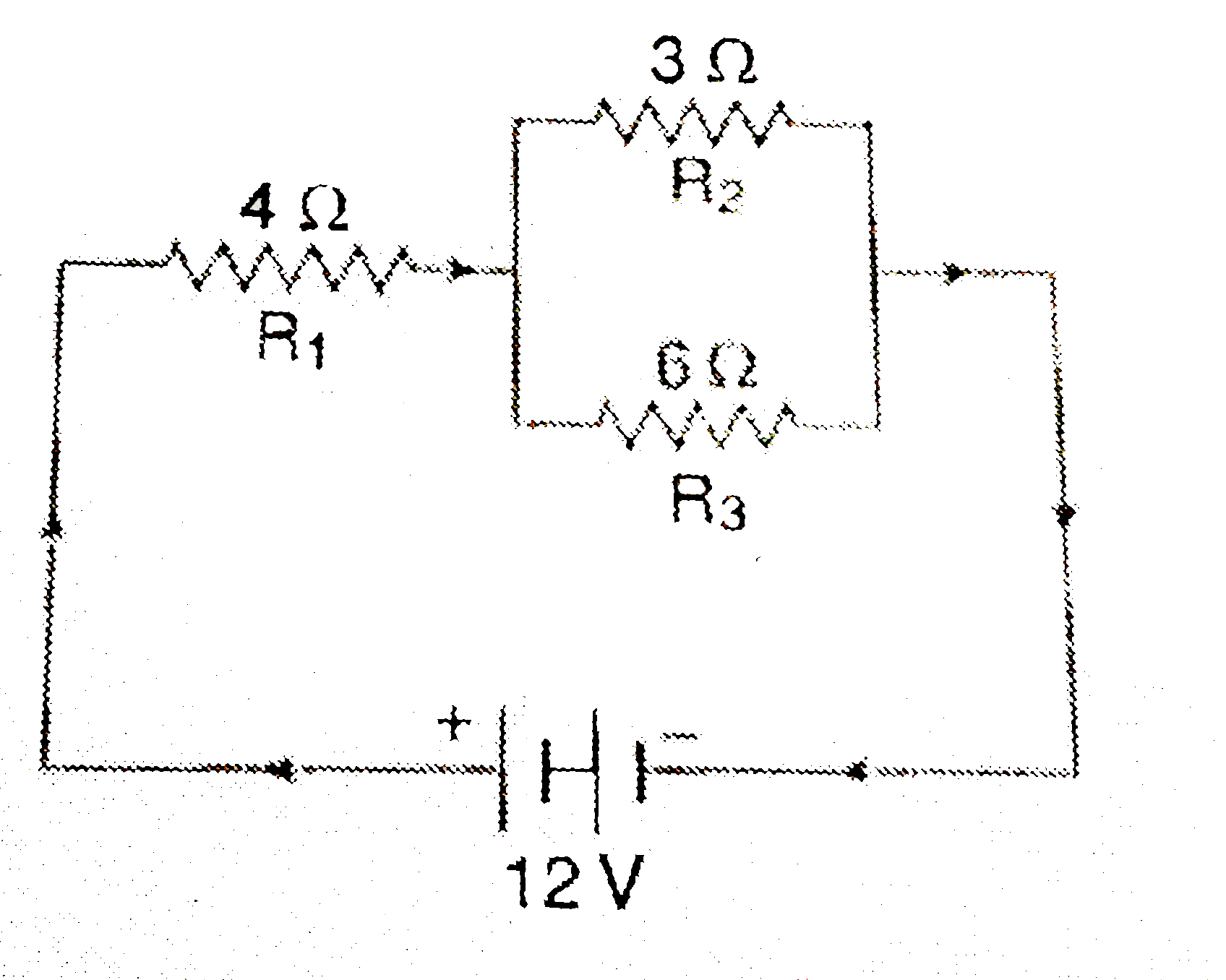
- The circuit diagram given below shows the combination of three resisto...
Text Solution
|
- If in Fig. 12.12, R(1)=10Omega, R(2)=40Omega, R(3)=30Omega, R(5)=60Ome...
Text Solution
|
- In the circuit diagram given alongside, find: (i) total resistance o...
Text Solution
|
- The circuit diagram given below shows the combination of three resisto...
Text Solution
|
- In the circuit diagram given below, three resistors R(1),R(2), and R(3...
Text Solution
|
- In the given circuit, calculate - (a) the total resistance of the circ...
Text Solution
|
- निम्न परिपथ आरेख में , ज्ञात कीजिए : परिपथ का तुल्य - प्रतिरोध ...
Text Solution
|
- एक अज्ञात वि.वा. बल E का सेल जिसका आन्तरिक प्रतिरोध r है दो अज...
Text Solution
|
- In the circuit diagram given below, three resistors R(1),R(2) and R(3)...
Text Solution
|