A
B
C
D
Text Solution
Verified by Experts


Topper's Solved these Questions
Similar Questions
Explore conceptually related problems
FIITJEE-GMP ASSESMENT-Objective problems
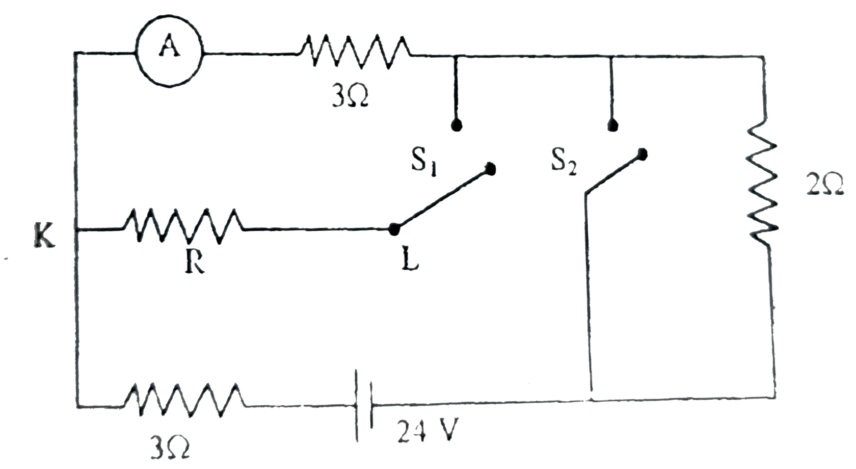
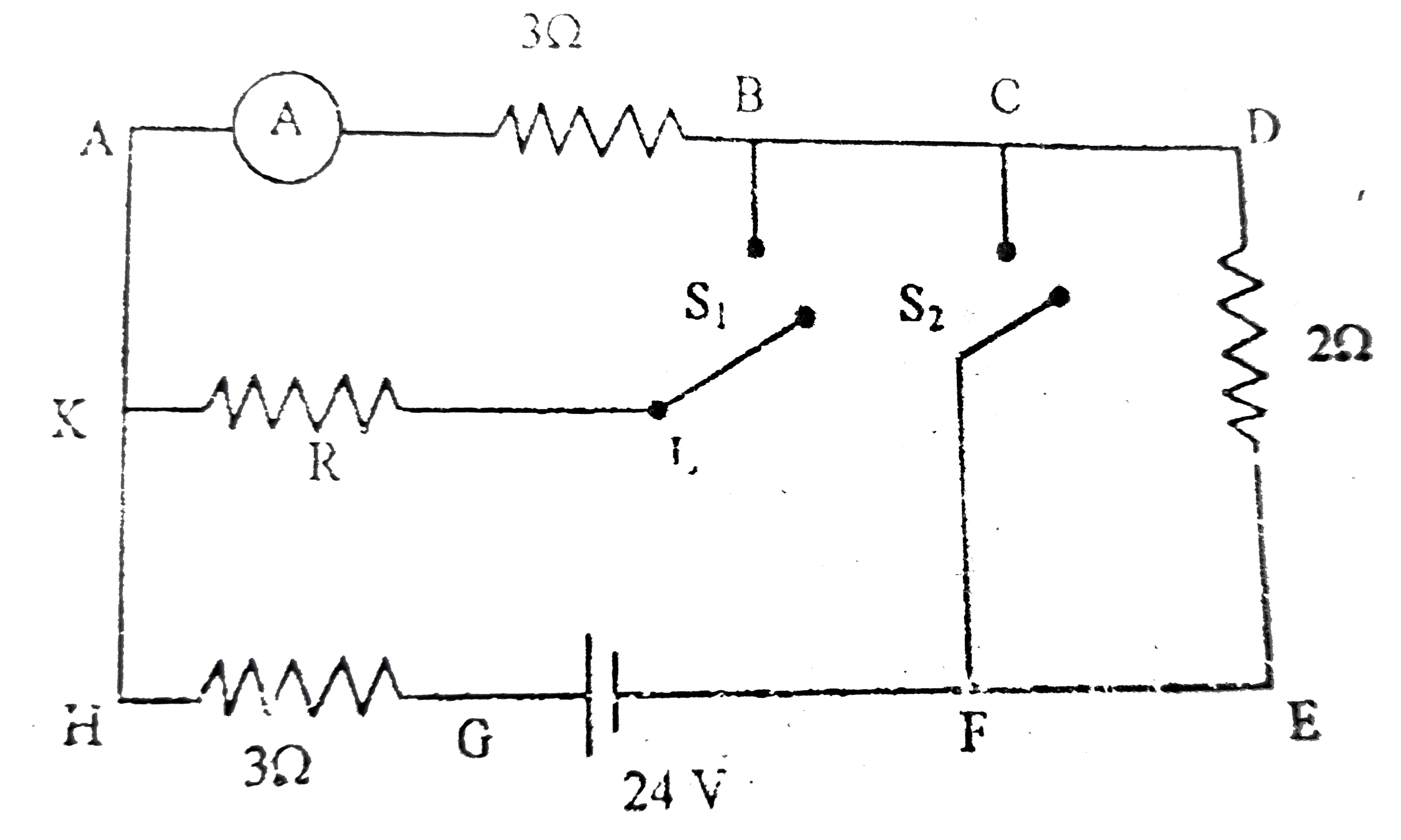
- In the circuit shown in the figure, the ideal ammeter reading for curr...
Text Solution
|
- A square plate of mass 10 kg and side 20 m is moving along the groove ...
Text Solution
|
- Two geometrically identical homogeneous balls are manufactured of diff...
Text Solution
|
- A metal plate of area 0.10 m^(2) is connected to a 0.04 kg mass via a ...
Text Solution
|
- A cubical transparent slab is used as a paper weight. What should be t...
Text Solution
|
- An object of size 2cm is placed at a distance of 40cm from a glass len...
Text Solution
|
- A thin and light thread of sufficient length L is attached to a wire f...
Text Solution
|
- An ice floe is floating in the sea. The part which is above the water ...
Text Solution
|
- A capillary tube is made of glass of refractive index n'. The outer ra...
Text Solution
|
- The room temperature charges by a small amount from T to T+DeltaT (on ...
Text Solution
|
- A ray of light, travelling parallel to diameter of a sphere enters the...
Text Solution
|
- Two mirror M(1) and M(2) make an angle phi with line AB. A point sourc...
Text Solution
|
- A Bohr hydrogen atom at rest in free space undergoes a transition from...
Text Solution
|
- In a certain region of space a uniform and constant electric field and...
Text Solution
|
- A metallic disc of radius r is made of a material of negligible resist...
Text Solution
|
- Two fixed identical metallic spheres A and B of radius R=50cm each are...
Text Solution
|
- A non conducting infinite rod is placed along the z-axis the upper hal...
Text Solution
|
- A insulating cylindrical rod of diameter d and length l(l gt gt d) has...
Text Solution
|
- The space has electromagnetic field which is given as vecB= -B(0)hatk ...
Text Solution
|
- An ideal monatomic gas undergoes a cyclic process ABCA as shown in the...
Text Solution
|