Home
Class 12
PHYSICS
(i) Identify the logic gates marked P an...

(i) Identify the logic gates marked P and Q in the given logic circuit Fig.

(ii) Write down the output at X for the inputs `A=0, B=0` and `A=1, B=1`.

Promotional Banner

Topper's Solved these Questions

  • SEMICONDUCTORS

    BANSAL|Exercise Exercise-4 Section-B|6 Videos
  • MASTER PRACTICE PROBLEM

    BANSAL|Exercise Additional topic|70 Videos
  • TEST PAPERS

    BANSAL|Exercise PHYSICS PART C|14 Videos

Similar Questions

Explore conceptually related problems

(i) Identify the logic gates marked P and Q in the given logic circuit. (ii) Write down the output at X for the inputs A = 0 , B = 0 and A = 1 , B = 1.

Identify the logic gates marked P and Q in the given logic circuit Fig. Write down then output at X for the inputs (i) A=0,B=0 and (ii) A=1, B=1 .

Identify the logic gate markeed P and Q in the given logic circuit Fig . Write down the output at X for the inputs (i) A=0,B=0 and (ii) A=1, B=1 .

Identify the logic gates marked X, Y in the given logic circuit Fig. Write down then output at y, when (i) A=0,B=0 and (ii) A=1, B=1 .

Identify the logic gates marked P and Q in the circuit Fig. Write the truth table for this combination.

Identify the logic gates marked P and Q in the given logic circuit. Write down the Boolean expression for this logic circuit and truth table.

Identify the logic gates marked X,Y in Fig. MTP 1.1. write down the output at y, when A=1,B=1 and A=0 and B=0.

Identify the logic gates marked X and Y in Fig.Write down the output at y, when A=1, B=1 and A=0,B=1 |{:(A,B,y',y),(1,1,0,1),(0,1,1,1):}:|

Identify the logic gate equivalent to the circuit shown in the Fig.Draw the truth table for all possible values of inputs A and B.

BANSAL-SEMICONDUCTORS-CBSE Question
  1. How does the resistivity of (i) a conductor and (ii) a semiconductor v...

    Text Solution

    |

  2. Distinguish between conductor (or metals), semiconductors and insulato...

    Text Solution

    |

  3. (a). Explains briefly with the help of a circuit diagram how V-I chara...

    Text Solution

    |

  4. Explain (i) forward biasing (ii) reverse biasing of a P-N junction dio...

    Text Solution

    |

  5. Distinguish between conductor (or metals), semiconductors and insulato...

    Text Solution

    |

  6. Two semiconductor materials X and Y shown in the given figure, are mad...

    Text Solution

    |

  7. Draw the circuit diagram of a common emitter amplifier using n-p-n tra...

    Text Solution

    |

  8. Expalin the formation of energy band in solids. Draw energy band diagr...

    Text Solution

    |

  9. Distinguish between intrinsic semiconductor and p-type semiconductor. ...

    Text Solution

    |

  10. The give inputs A, B are fed to a 2-input NAND gate. Draw the output w...

    Text Solution

    |

  11. The output of a 2-input AND gate is fed to a NOT gate. Give the name o...

    Text Solution

    |

  12. Draw a circuit diagram of a transistor amplifier in CE configuration. ...

    Text Solution

    |

  13. Explain (i) forward biasing (ii) reverse biasing of a P-N junction dio...

    Text Solution

    |

  14. In V-I characteristics of a p-n junction diode, why is the current und...

    Text Solution

    |

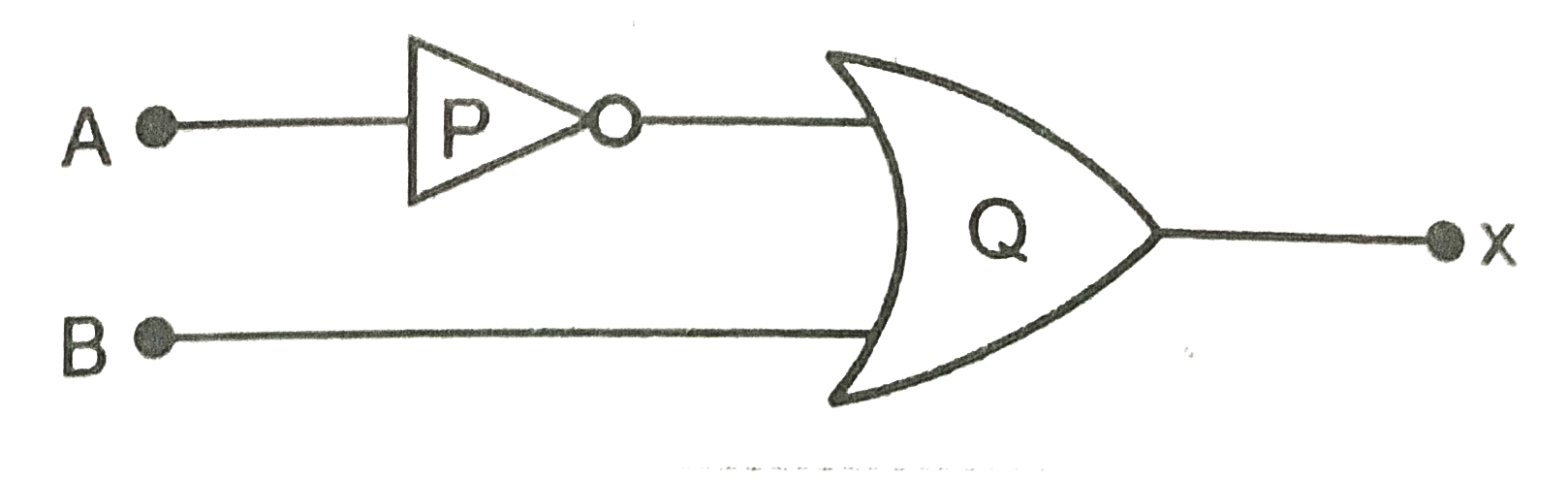
  15. (i) Identify the logic gates marked P and Q in the given logic circuit...

    Text Solution

    |

  16. What happens to the width of depletion layer of a p-n junction when it...

    Text Solution

    |

  17. Draw a circuit diagram of a full-wave rectifier. Explain its working p...

    Text Solution

    |

  18. You are given a circuit below. Write its truth table. Hence, identify ...

    Text Solution

    |

  19. Explain the formation of depletion layer and potential barrier in p-n ...

    Text Solution

    |

  20. Draw a circuit diagram of a full-wave rectifier. Explain its working p...

    Text Solution

    |