A
B
C
D
Text Solution
Verified by Experts
The correct Answer is:


Topper's Solved these Questions
Similar Questions
Explore conceptually related problems
ERRORLESS -ELASTICITY-Graphical Question
- The graph shown was obtained from experimental measurements of the per...
Text Solution
|
- A graph is shown between stress and strain for a metal. The part in wh...
Text Solution
|
- In the above graph, point B indicates.
Text Solution
|
- In the graph, point D indicates
Text Solution
|
- The strain-stress curves of three wire of different materials are show...
Text Solution
|
- The diagram shows a force extension graph for a rubber band, consider ...
Text Solution
|
- The stress versus strain graphs for wires of two materials A and B are...
Text Solution
|
- The load versus elongation graph for four wires of the same material i...
Text Solution
|
- The adjacent graph shows the estension (Deltal) of a wire of length 1m...
Text Solution
|
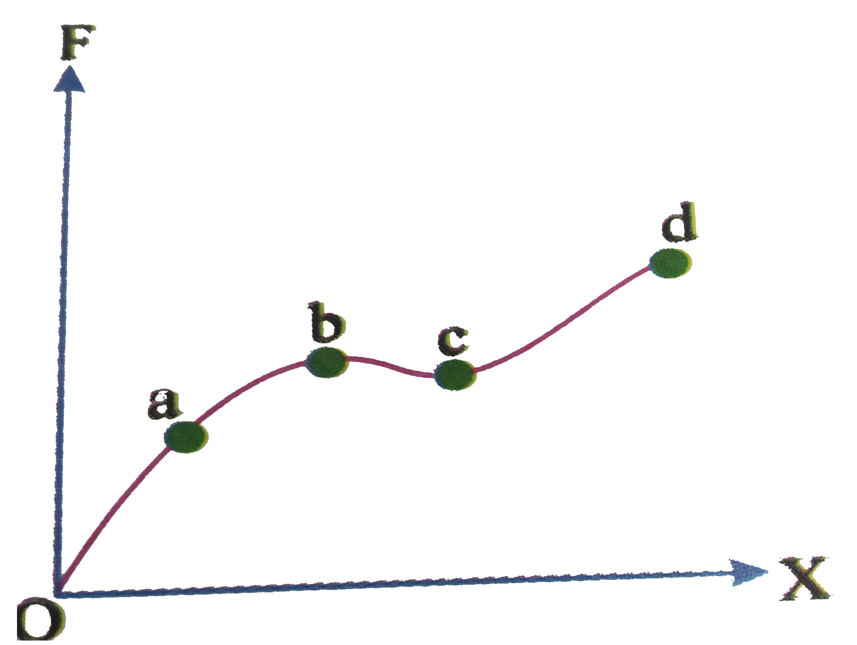
- The diagram represents the applied force per unit area (F) with the...
Text Solution
|
- The graph shows the behaviout of a length of wire in the region for wh...
Text Solution
|
- The potential energy U between two molecules as a function of the dist...
Text Solution
|
- The valve of force constant between the applied the applied elastic fo...
Text Solution
|
- The diagram shows stress v/s strain curve for the materials A and B. F...
Text Solution
|
- Which one of the following is the Young's modulus (in N/m) for the wir...
Text Solution
|
- The diagram shows the change x in the length of the uniform wire cause...
Text Solution
|
- A student plots a graph from his reading on the determination of Young...
Text Solution
|
- the points of maximum and minimum attraction in the curve between pote...
Text Solution
|
- The stress strain curves for brass, steel and rubber are shown in the ...
Text Solution
|