Text Solution
Verified by Experts
The correct Answer is:


Topper's Solved these Questions
Similar Questions
Explore conceptually related problems
PHYSICS GALAXY - ASHISH ARORA-CAPACITANCE-UNSOLVED NUMERICAL PROBLEMS
- A parallel plate capacitor of capacitance 0.1muF is shown in the figur...
Text Solution
|
- Two identical planar capacitor connected in parallel and charged to a ...
Text Solution
|
- A parallel - plate capacitor of plate area A and plate separation d is...
Text Solution
|
- A parallel plate vacuum capacitor with plate area A and separation x h...
Text Solution
|
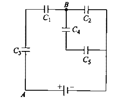
- Find the equivalent capacitance across terminals A and B in the circui...
Text Solution
|
- In the circuit shown in figure, capacitor A has capacitance C(1)=2muF ...
Text Solution
|
- In the circuit shown in figure C(1)=5muF, C(2)=29muC, C(3)=6muF, C(4)=...
Text Solution
|
- Find the equivalent capacitance between terminals A & C, if each capac...
Text Solution
|
- In the given network if potential difference between p and q is 2V and...
Text Solution
|
- The plates of a parallel plate capacitor are separated by a distance d...
Text Solution
|
- Two parallel plate capacitors of capacitance C and 2C are connected in...
Text Solution
|
- A charge 200mC is imparted to .each of the two identical parallel plat...
Text Solution
|
- A circuit is shown in figure. Find the charge on the condenser having ...
Text Solution
|
- A solid conducting sphere of radius 10 cm is enclosed by a thin metall...
Text Solution
|
- Three capacitors each having capacitance C=2 muF are connected with a ...
Text Solution
|
- Consider the situation shown in figure. The plates of the capacitor ha...
Text Solution
|
- In the circuit shown in figure find the equivalent capacitance between...
Text Solution
|
- A capacitor is made of a flat plate of area A and another plate is ben...
Text Solution
|
- A parallel -plate capacitor with the plate area 100cm^2 and the separa...
Text Solution
|
- Figure shows a capacitor having three layers of equal thickness and sa...
Text Solution
|